Presentation of obstacle detection system
An obstacle detection system is a device or set of devices that are designed to detect the presence of obstacles in a specific area or environment. These systems can be used in a variety of applications, including robotics, autonomous vehicles, and industrial automation.
There are several different types of obstacle detection systems, including:
- Ultrasonic sensors: These sensors use high-frequency sound waves to detect obstacles. They emit a sound wave and measure the time it takes for the wave to bounce back. The sensor can then calculate the distance to the obstacle.
- Infrared sensors: These sensors use infrared light to detect obstacles. They emit a beam of infrared light and measure the intensity of the light that is reflected back. The sensor can then calculate the distance to the obstacle.
- Lidar sensors: These sensors use lasers to detect obstacles. They emit a laser beam and measure the time it takes for the beam to bounce back. The sensor can then calculate the distance to the obstacle.
- Stereoscopic cameras: These cameras use two or more lenses to detect obstacles. They take two or more images of the same scene and compare them to identify obstacles.
- Machine learning-based systems: These systems use artificial intelligence and machine learning to detect obstacles. They learn from training data and can improve over time.
Obstacle detection systems are used in a wide range of applications, such as self-driving cars, drones, and industrial automation, to name a few.
An obstacle detection system controlled by a Micro:bit can be created using sensors such as ultrasonic, infrared, or lidar sensors, which can be connected to the Micro:bit board via the edge connector pins. The Micro:bit can then be programmed to interact with the sensor and detect obstacles.
For example, an ultrasonic sensor can be connected to the Micro:bit and programmed to emit a sound wave and measure the time it takes for the wave to bounce back. The Micro:bit can then calculate the distance to the obstacle and output the information to an LED matrix, a speaker or even to another device.
Similarly, an infrared sensor can be connected to the Micro:bit and programmed to emit a beam of infrared light and measure the intensity of the light that is reflected back. The Micro:bit can then calculate the distance to the obstacle and output the information to an LED matrix, a speaker or even to another device.
A lidar sensor can also be connected to the Micro:bit and programmed in a similar way, emitting a laser beam and measuring the time it takes for the beam to bounce back. The Micro:bit can then calculate the distance to the obstacle and output the information to an LED matrix, a speaker or even to another device.
Purpose of this project:
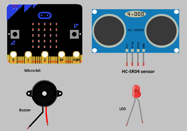
In this project we will create an alarm system with microb:bit. This alarm mainly uses an HC-SR04 sensor, buzzer and LED.
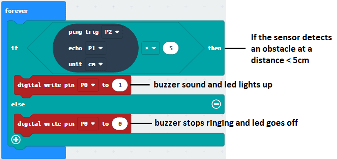
When the ultrasonic sensor detects an obstacle at a distance < 5cm, the micro:bit board orders the buzzer to ring and the red LED to light up.
Required components
Micro:bit board
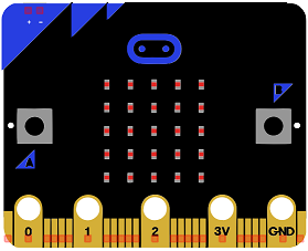
Micro:bit is a small, low-cost microcontroller board that was developed by the Micro:bit Educational Foundation for use in computer education. It is designed to be easy to use and accessible to a wide range of users, including children and beginners. The Micro:bit board measures about 4cm by 5cm and features a 25-pin edge connector, a 5×5 LED matrix, two programmable buttons, an accelerometer, a compass, a Bluetooth Low Energy (BLE) module, and a USB connector.
The Micro:bit is programmed using a variety of programming languages such as Python, JavaScript, and Microsoft Block Editor. It can be used to control a wide range of devices and projects, including robots, drones, lights, and more. The board can be powered by a USB cable or a 3V coin cell battery and can be programmed using a computer or mobile device.
The Micro:bit is widely used in education, providing a hands-on learning experience for students of all ages to learn computer programming, logic, and problem-solving. It’s also used by hobbyist and makers to create fun and interactive projects.
Microbit GPIO board
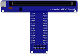
A Micro:bit GPIO (General Purpose Input/Output) Expansion Board is an accessory that can be used to extend the capabilities of a Micro:bit by providing additional input/output (I/O) pins. These pins can be used to connect sensors and actuators, such as LEDs, buttons, motors, and other electronic components.
The expansion board typically connects to the Micro:bit using a standard edge connector and provides a set of male headers that can be used to connect external components.
Ultrasonic sensor (HC-SR04)
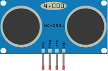
The HC-SR04 is an ultrasonic distance sensor that can be used for obstacle detection. It can measure distances from 2 cm to 400 cm with an accuracy of about 3 mm. The sensor consists of an ultrasonic transmitter and receiver, as well as a control circuit.
To use the HC-SR04 with a Micro:bit, you will need to connect the sensor to the Micro:bit‘s edge connector pins. The HC-SR04 has four pins: Vcc, Trig, Echo, and GND. The Vcc and GND pins should be connected to the Micro:bit‘s 3V and GND pins, respectively. The Trig pin should be connected to a Micro:bit pin that can be used to send digital signals (e.g. pin 0) and the Echo pin should be connected to a Micro:bit pin that can be used to receive digital signals (e.g. pin 1).
Once the HC-SR04 is connected to the Micro:bit, you can use the Micro:bit‘s built-in blocks or the Python programming language to write code that interacts with the sensor. The Micro:bit will send a signal to the Trig pin to initiate a measurement, and then listen for a signal on the Echo pin to determine the distance to an obstacle.
For example, you can use a “Pulse” block to send a signal to the Trig pin and a “pulses_in” block to receive the signal on the Echo pin and calculate the duration of the pulse. Then, you can use the speed of sound (about 340 m/s) to calculate the distance to the obstacle. The Micro:bit can then output the distance to an LED matrix, a speaker, or even to another device.
Buzzer
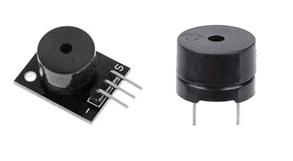
A buzzer can be used as an indicator in an obstacle detection system controlled by a Micro:bit. The buzzer can be connected to the Micro:bit and programmed to emit a sound when an obstacle is detected.
For example, you can use an ultrasonic distance sensor such as the HC-SR04 to detect obstacles and the Micro:bit to calculate the distance to the obstacle. When the distance is below a certain threshold (indicating the presence of an obstacle), the Micro:bit can send a signal to the buzzer to emit a sound.
To connect the buzzer to the Micro:bit, you will need to connect one lead of the buzzer to a Micro:bit pin that can be used to send digital signals (e.g. pin 0) and the other lead of the buzzer to the Micro:bit’s GND pin.
You can use the Micro:bit’s built-in blocks or the Python programming language to write code that interacts with the sensor and the buzzer. For example, you can use a “Pulse” block to send a signal to the Trig pin of the HC-SR04 sensor, a “pulses_in” block to receive the signal on the Echo pin and calculate the duration of the pulse, and then use the speed of sound (about 340 m/s) to calculate the distance to the obstacle.
Then you can use an “if” block to check if the distance is less than a certain threshold and if so, use a “music” block to play a melody on the buzzer.
Keep in mind that the HC-SR04 sensor has a minimum detection range of 2cm and the accuracy decreases with distance, also the sound emitted by the buzzer could be too loud for certain applications.
1 resistance 220Ω
![]()
Resistance is a measure of a material’s opposition to the flow of electric current. It is measured in ohms (Ω) and is represented by the symbol “R”. The more resistance a material has, the less current will flow through it when a given voltage is applied. Conversely, the less resistance a material has, the more current will flow through it when a given voltage is applied.
1 red LED
![]()
A red LED (light-emitting diode) is a type of diode that emits light in the red part of the visible spectrum when an electric current is passed through it. LEDs are semiconductor devices that convert electrical energy into light energy. They are widely used in various electronic devices and systems, such as displays, indicator lights, flashlights, and traffic signals.
connecting wires

Connecting wires are used to connect various components in an electronic circuit. They allow for the transfer of electricity, data, or signals between different devices and components.
When connecting wires to an Arduino or other microcontroller, it is important to pay attention to the correct pinout. The pinout refers to the arrangement of pins on the microcontroller and the corresponding function of each pin. The Arduino pinout can be found in the documentation provided by the manufacturer, or in various resources available online.
test plate

A test plate, also known as a test jig, is a device used to test electronic circuits and components. It is a board or plate that has been designed to hold and connect various components and devices in a specific configuration, allowing for the easy testing and measurement of their performance.
A test plate can be used to test various types of electronic circuits and components, such as microcontrollers, sensors, and actuators. It typically includes connectors and sockets for connecting wires, power supply and measurement devices such as multimeters, oscilloscopes, and power supplies.
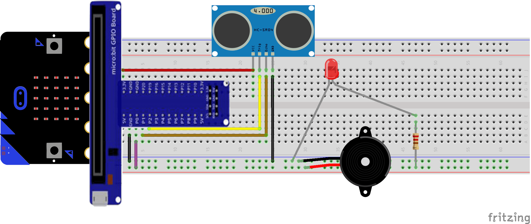
Mounting
To complete the assembly,
- the red LED and buzzer can be connected to pin P0 of the micro:bit
- the TRIGGER pin of the ultrasonic sensor to pin P1 of the micro:bit board
- the echo pin of the ultrasonic sensor to pin P2 of the micro:bit board.
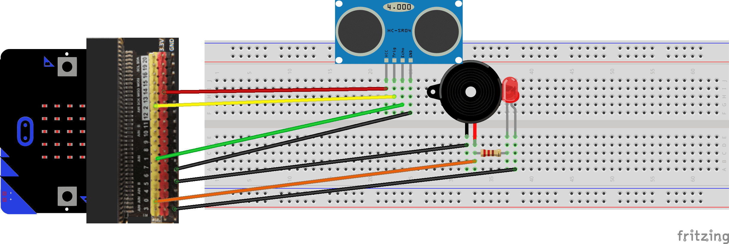
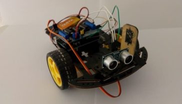
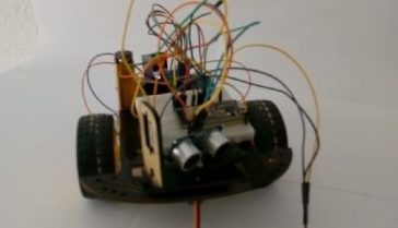
The mounting methods are numerous and here are some examples:
Mounting (1)
Mounting (2)
Makecode programme
Here is the makecode program of the audible alarm system:
You can also see

3 commentaires
Leave a comment


Recent tutorials


Most viewed tutorials


Most commented tutorials


Scroll to Top
manuelxfjnr.webdesign96.com 03-03-2323
Howdy I am so delighted I found your web site, I really found you by error, while I was researching on Google for something else, Regardless I am here now and would just like to say thanks a lot for a marvelous post and a all round entertaining blog (I also love the theme/design), I don't have time to browse it all at the minute but I have book-marked it and also included your RSS feeds, so when I have time I will be back to read a great deal more, Please do keep up the fantastic work.
vitaminler.ra6.org 19-01-2323
I do agree with all the ideas you've offered to your post. They're very convincing and can definitely work. Nonetheless, the posts are too quick for novices. May just you please lengthen them a bit from next time? Thanks for the post.
writing.ra6.org 30-12-2222
Appreciating the commitment you put into your website and in depth information you offer. It's good to come across a blog every once in a while that isn't the same outdated rehashed information. Wonderful read! I've bookmarked your site and I'm including your RSS feeds to my Google account.