Micro:bit Servo motor
Control a servomotor using the buttons on the Micro:bit card
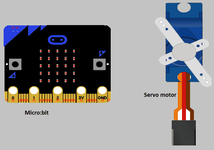
A servo motor can be controlled by a Micro:bit by sending control signals to the servo’s control pin. The Micro:bit can generate these control signals using a pulse-width modulation (PWM) output pin.
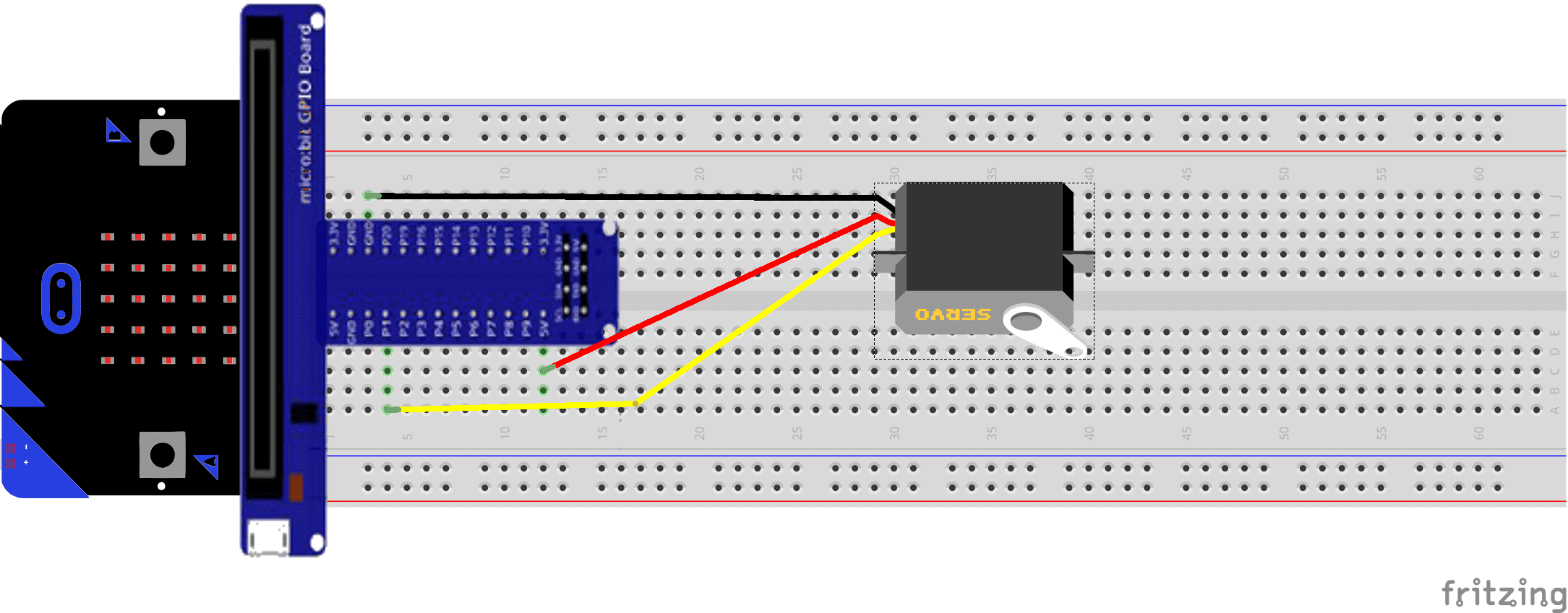
To control a servo motor with a Micro:bit, you will need to connect the servo to the Micro:bit‘s PWM pin. You can use any of the Micro:bit‘s PWM-enabled pins, such as pin 0, 1, 2, 8, 12, and 16. The servo’s control pin should be connected to the chosen PWM pin, and the servo’s power and ground pins should be connected to the Micro:bit‘s 3V and GND pins, respectively.
Purpose of this tutorial:
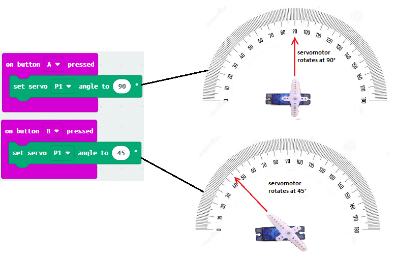
In this tutorial we will control the servomotor using the two buttons A and B of the micro: bit: If you press button A, the servomotor positions itself at the 90 ° angle. If you press button B, the servomotor positions itself at the 45 ° angle.
Components required
Micro:bit board
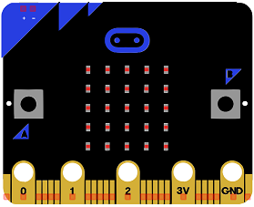
Micro:bit is a small, low-cost microcontroller board that was developed by the Micro:bit Educational Foundation for use in computer education. It is designed to be easy to use and accessible to a wide range of users, including children and beginners. The Micro:bit board measures about 4cm by 5cm and features a 25-pin edge connector, a 5×5 LED matrix, two programmable buttons, an accelerometer, a compass, a Bluetooth Low Energy (BLE) module, and a USB connector.
The Micro:bit is programmed using a variety of programming languages such as Python, JavaScript, and Microsoft Block Editor. It can be used to control a wide range of devices and projects, including robots, drones, lights, and more. The board can be powered by a USB cable or a 3V coin cell battery and can be programmed using a computer or mobile device.
The Micro:bit is widely used in education, providing a hands-on learning experience for students of all ages to learn computer programming, logic, and problem-solving. It’s also used by hobbyist and makers to create fun and interactive projects.
Microbit GPIO board
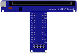
A Micro:bit GPIO (General Purpose Input/Output) Expansion Board is an accessory that can be used to extend the capabilities of a Micro:bit by providing additional input/output (I/O) pins. These pins can be used to connect sensors and actuators, such as LEDs, buttons, motors, and other electronic components.
The expansion board typically connects to the Micro:bit using a standard edge connector and provides a set of male headers that can be used to connect external components.
Servo motor
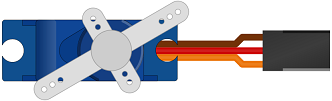
A servo motor is a type of rotary actuator that is used to control the position of a shaft or other mechanical component. It is a closed-loop control system that consists of a motor, a sensor (such as a potentiometer), and a control circuit.
The motor in a servo system is typically a small DC motor, which is used to rotate the shaft. The sensor, such as a potentiometer, is used to measure the position of the shaft and provide feedback to the control circuit. The control circuit uses this feedback to compare the desired position of the shaft to its actual position and adjust the motor’s power accordingly.
Servo motors are commonly used in a wide range of applications, such as robotics, automation, and model aircraft, because of their ability to rotate to a specific position, hold that position, and rotate at different speeds. They come in different sizes and shapes, with different torque and speed specifications.
Typically, servo motors are controlled by sending control signals, typically in the form of Pulse Width Modulation (PWM) signals, to the servo’s control pin. The duration of these pulses determines the position of the servo’s shaft. Servo motors are controlled by the duration of the high signal of the PWM signal, and the width of the high signal determines the position of the servo motor.
connecting wires

Connecting wires are used to connect various components in an electronic circuit. They allow for the transfer of electricity, data, or signals between different devices and components.
When connecting wires to an Arduino or other microcontroller, it is important to pay attention to the correct pinout. The pinout refers to the arrangement of pins on the microcontroller and the corresponding function of each pin. The Arduino pinout can be found in the documentation provided by the manufacturer, or in various resources available online.
test plate

A test plate, also known as a test jig, is a device used to test electronic circuits and components. It is a board or plate that has been designed to hold and connect various components and devices in a specific configuration, allowing for the easy testing and measurement of their performance.
A test plate can be used to test various types of electronic circuits and components, such as microcontrollers, sensors, and actuators. It typically includes connectors and sockets for connecting wires, power supply and measurement devices such as multimeters, oscilloscopes, and power supplies.
Mounting
The connection is almost always the same and will be done using 3 wires, the main colors of which you may encounter:
- Red: + 5V power supply.
- Black or brown: common to connect to the micro: bit GND
- Pin Orange, yellow or white: positioning signal sent by the micro: bit card.
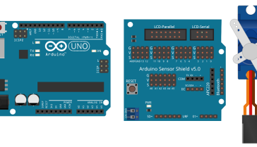
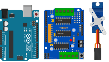
There are several mounting methods.
Makecode program
Here is the makecode program which allows you to control a servomotor using the buttons on the micro: bit card. Note: You must go to Extensions to import the servo extension.
You can also see

0 commentaire
Leave a comment


Recent tutorials


Most viewed tutorials


Most commented tutorials


Scroll to Top