The HC-SR04 ultrasonic sensor is a popular sensor for measuring distance with Arduino. It uses sonar to determine the distance to an object by sending out a sound wave at a high frequency and measuring the time it takes for the sound wave to bounce back.
To use the HC-SR04 sensor with an Arduino, you will need to connect the sensor to the Arduino board using wires. The HC-SR04 has four pins: Vcc, Trig, Echo, and GND. Vcc and GND should be connected to the 5V and GND pins on the Arduino, Trig should be connected to a digital pin (for example, pin 8), and Echo should be connected to another digital pin (for example, pin 9).
Once the sensor is connected, you can use the Arduino’s pulseIn() function to measure the duration of the sound wave’s return trip. You can then use this duration to calculate the distance to an object using the formula: distance = (duration/2) * 0.034.
Purpose of this tutorial:
In this tutorial, we will learn together how to use an HC-SR04 reference ultrasonic distance sensor with an Arduino board.we will test the accuracy of the measurements in various situations and display the results from the HC-SR04 Ultrasonic Sensor on an LCD i2c Display.
HC-SR04 sensor:
An ultrasonic distance sensor uses the same principle as a laser sensor, but using sound waves (inaudible) instead of a beam of light. They are much cheaper than a laser sensor, but also much less precise. However, unlike infrared sensors, ambient light and the opacity of the surface in front of the sensor do not affect the measurement.
The HC-SR04 sensor is a low cost ultrasonic sensor. This sensor operates with a supply voltage of 5 volts, has a measurement angle of approximately 15° and allows distance measurements between 2 centimeters and 4 meters with an accuracy of 3mm (in theory, in practice That is not exactly correct).
The operating principle of the sensor is entirely based on the speed of sound.
Here is how a measurement takes place:
-
We send a HIGH pulse of 10µs on the TRIGGER pin of the sensor.
- The sensor then sends a series of 8 ultrasonic pulses at 40KHz
-
Ultrasound travels through the air until it hits an obstacle and returns in the other direction to the sensor.
-
The sensor detects the echo and closes the measurement run.
The signal on the ECHO pin of the sensor stays HIGH during steps 3 and 4, which allows the duration of the round trip of the ultrasound to be measured and therefore the distance to be determined.
LCD i2c Display:
An LCD i2c screen (Liquid Crystal Display) or liquid crystal display in French is a device that displays characters while consuming relatively little electricity, which is why it is found in many electronic projects and on all types of devices.
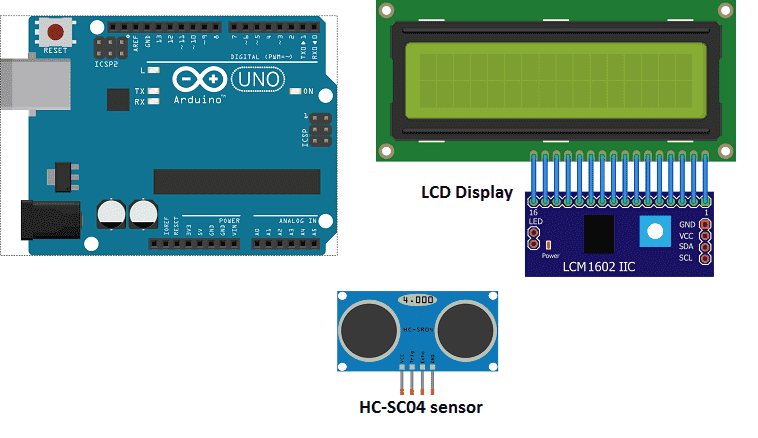
Necessary components
Arduino UNO
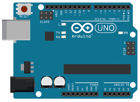
The Arduino UNO is a microcontroller board based on the ATmega328P. It has 14 digital input/output pins, 6 analog inputs, a 16 MHz quartz crystal, a USB connection, a power jack, an ICSP header, and a reset button. It is the most popular and widely used board among the Arduino boards.
The Arduino UNO can be programmed using the Arduino programming language, which is based on C++. It uses a simple and intuitive programming environment, making it easy for beginners to get started with microcontroller programming.
The Arduino UNO can be connected to various sensors and actuators to control different devices and perform different tasks. For example, it can be used to control motors, read data from sensors, display information on an LCD screen, and communicate with other devices via serial communication protocols such as I2C and SPI.
The Arduino UNO can also be powered by a USB cable or an external power supply, making it easy to use in a wide range of projects and applications. It’s compatible with a wide range of shields (expansion boards) that adds functionality to the board, such as Ethernet, WiFi, and Bluetooth, and it’s widely supported by a strong and active community, which provides a lot of tutorials, examples and libraries to help users to get the most of the board.
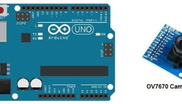
HC-SR04 ultrasonic sensor
The HC-SR04 ultrasonic sensor is a low-cost, easy-to-use distance sensor that can be used to measure distances from 2cm to 400cm. It uses sonar to determine the distance to an object by sending out a sound wave at a high frequency and measuring the time it takes for the sound wave to bounce back. The sensor has four pins: Vcc, Trig, Echo, and GND. Vcc and GND are used to power the sensor, Trig is used to initiate the distance measurement, and Echo is used to receive the sound wave’s return trip.
The sensor sends out an 8-cycle burst of 40kHz sound and listens for the echo. The time for the echo to return is proportional to the distance of the object. The duration of the echo pulse is converted to a distance value by using the formula: distance = (duration/2) * 0.034.
To interface HC-SR04 with an Arduino, you will need to connect the sensor to the Arduino board using wires. Connect the Vcc and GND to 5V and GND pins on the Arduino, Trig to a digital pin (for example, pin 8) and Echo to another digital pin (for example, pin 9).
This sensor is commonly used in robotic and automation projects, obstacle avoidance, and distance measurement applications.
LCD I2C 160A display
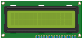
An LCD I2C 160A display is a type of liquid crystal display (LCD) that uses the Inter-Integrated Circuit (I2C) protocol to communicate with the controller or host device. The “160A” in the name likely refers to the display’s dimensions, with a screen size of 160×128 pixels. I2C is a communication protocol that allows multiple devices to connect to a single bus and communicate with one another using only two wires (SDA and SCL). This can make it a more efficient and cost-effective solution for connecting multiple devices in a project, as compared to using separate wires for each device.
onnecting wires

Connecting wires are used to connect various components in an electronic circuit. They allow for the transfer of electricity, data, or signals between different devices and components.
When connecting wires to an Arduino or other microcontroller, it is important to pay attention to the correct pinout. The pinout refers to the arrangement of pins on the microcontroller and the corresponding function of each pin. The Arduino pinout can be found in the documentation provided by the manufacturer, or in various resources available online.
test plate

A test plate, also known as a test jig, is a device used to test electronic circuits and components. It is a board or plate that has been designed to hold and connect various components and devices in a specific configuration, allowing for the easy testing and measurement of their performance.
A test plate can be used to test various types of electronic circuits and components, such as microcontrollers, sensors, and actuators. It typically includes connectors and sockets for connecting wires, power supply and measurement devices such as multimeters, oscilloscopes, and power supplies.
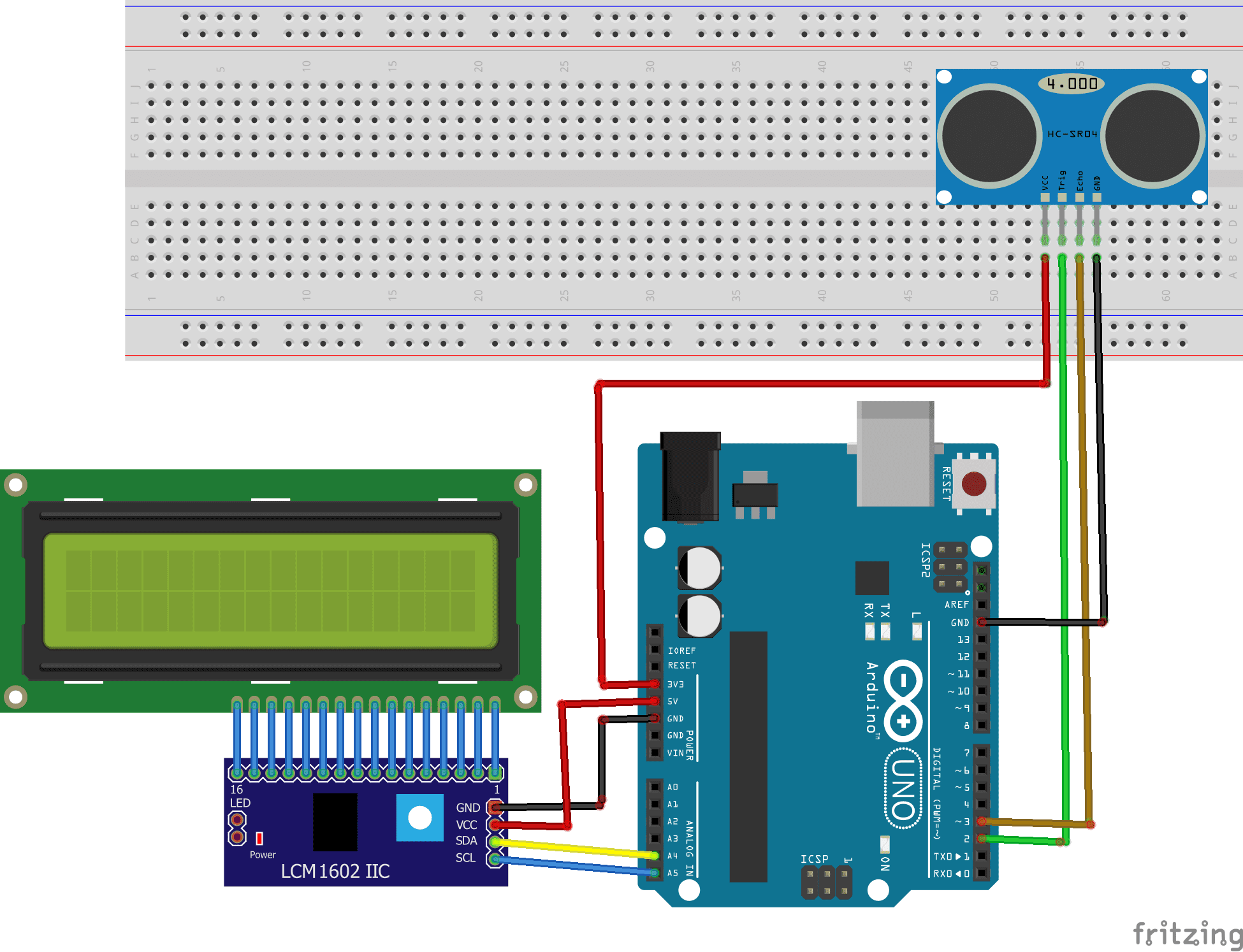
Mounting
For the HC-SR04 sensor we connect:
- The 3.3V power supply of the Arduino goes to the VCC pin of the sensor.
- The GND pin of the Arduino goes to the GND pin of the sensor.
- The digital Pin1 of the Arduino goes to the TRIGGER pin of the sensor.
- The digital Pin2 of the Arduino goes to the ECHO pin of the sensor.
For the LCD display we connect:
-
the SDA pin at the Arduino analog pin A4.
-
the SCL pin at the Arduino analog pin A5.
-
the VCC pin at the Arduino 5v pin.
-
the GND pin at the Arduino GND pin
Arduino program
Here is the program that displays the distance in cm that separates the ultrasonic sensor from an obstacle.
Note: you must import the library HCSR04.h for ultrasonic sensor and library LiquidCrystal_I2C.h for the LCD display.
|
1 2 3 4 5 6 7 8 9 10 11 12 13 14 15 16 17 18 19 20 21 22 |
#include <HCSR04.h> #include <LiquidCrystal_I2C.h> LiquidCrystal_I2C lcd(0x27, 20, 4); // Pins of HC-Sc04 sensor const int trigPin = 2; const int echoPin = 3; // initialization of the sensor with the pins UltraSonicDistanceSensor distanceSensor(trigPin, echoPin); void setup() { lcd.init(); } void loop() { lcd.backlight(); lcd.clear(); lcd.print("distance = "); lcd.setCursor(0,1); lcd.print(distanceSensor.measureDistanceCm()+1); lcd.print(" cm"); delay(500); } |
How the code works:
First, the trigger pin and the echo pin are defined. I call them trigPin and EchoPin. The trigger pin is connected to digital pin 2 and the echo pin to digital pin 3 on the Arduino.
Then you initialize the HC-SR04 sensor with the pins.
In the setup() you initialize 1602 I2C LCD screen.
In the loop() you trigger the sensor and the measured distance is displayed on a 1602 I2C LCD screen.
You can also see

0 commentaire
Leave a comment


Recent tutorials


Most viewed tutorials


Most commented tutorials


Scroll to Top