Presentation of automatic lighting system
An automatic lighting system is a system of lights that turn on and off automatically based on various conditions, such as time of day, presence of people, or ambient light levels. Such systems can be used to conserve energy and improve safety and convenience in buildings, outdoor spaces, and other areas.
There are several types of automatic lighting systems, which include:
- Time-based systems: These systems turn lights on and off based on a set schedule, such as turning on at sunset and turning off at sunrise.
- Occupancy-based systems: These systems use sensors to detect the presence of people and turn lights on when someone is in the area, and turn them off when the area is empty.
- Daylight harvesting systems: These systems use sensors to measure ambient light levels and adjust the light output of the fixtures accordingly.
- Combination systems: Some systems use a combination of the above methods to provide optimal lighting control.
These systems can be controlled through various ways, like, manual switches, push buttons, or by using a microcontroller, which can be programmed to perform specific lighting control functions.
The automatic lighting system can be connected to a relay in order to control the lighting fixtures, which can be turned on or off with the push button or through the control circuit.
An automatic lighting system with Arduino is a system that uses an Arduino microcontroller to control the lighting fixtures based on various conditions. The Arduino board is a small, low-cost computer that can be programmed to read input from sensors, perform calculations, and control output devices such as relays. This makes it an ideal platform for building an automatic lighting system.
To build an automatic lighting system with Arduino, the following steps can be followed:
- Connect sensors: Depending on the desired functionality, various sensors can be connected to the Arduino board, such as a light sensor to measure ambient light levels, or a motion sensor to detect the presence of people.
- Write the code: Using the Arduino programming language, the code can be written to read the sensor data, perform calculations, and control the relays. For example, the code can be written to turn on the lights when the ambient light level drops below a certain threshold or when motion is detected.
- Upload the code: The code can be uploaded to the Arduino board using a USB cable and the Arduino development software.
- Connect the relays: The relays can be connected to the Arduino board, and the lights can be connected to the relays. The relays can be controlled by the Arduino board, turning the lights on and off as programmed.
- Connect the push button: The push button can be connected to the arduino board through the digital input pin. The code can be written to perform different actions based on the push button state.
- Power supply: Finally, the arduino board and the other electronic components can be powered through a power supply or a battery.
Purpose of this project:
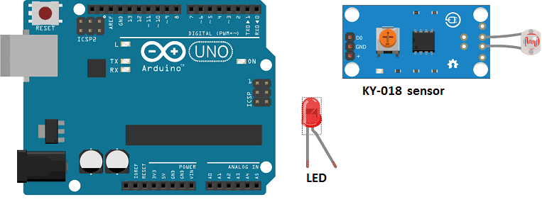
In this project an automatic lighting system with Arduino will be realized.
It consists of turning on an LED lamp when the room becomes dark and turning it off otherwise. It mainly uses a KY-018 light sensor.
Necessary components
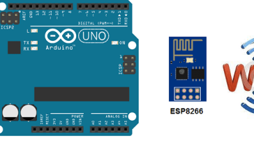
Arduino UNO
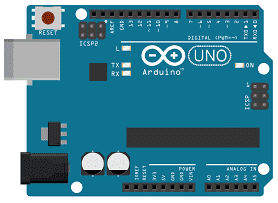
The Arduino UNO is a microcontroller board based on the ATmega328P. It has 14 digital input/output pins, 6 analog inputs, a 16 MHz quartz crystal, a USB connection, a power jack, an ICSP header, and a reset button. It is the most popular and widely used board among the Arduino boards.
The Arduino UNO can be programmed using the Arduino programming language, which is based on C++. It uses a simple and intuitive programming environment, making it easy for beginners to get started with microcontroller programming.
The Arduino UNO can be connected to various sensors and actuators to control different devices and perform different tasks. For example, it can be used to control motors, read data from sensors, display information on an LCD screen, and communicate with other devices via serial communication protocols such as I2C and SPI.
The Arduino UNO can also be powered by a USB cable or an external power supply, making it easy to use in a wide range of projects and applications. It’s compatible with a wide range of shields (expansion boards) that adds functionality to the board, such as Ethernet, WiFi, and Bluetooth, and it’s widely supported by a strong and active community, which provides a lot of tutorials, examples and libraries to help users to get the most of the board.
KY-018 sensor
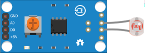
The KY-018 sensor is a photoresistor sensor module that is often used with Arduino and other microcontroller-based projects. A photoresistor is a type of resistor whose resistance decreases as the amount of light falling on it increases. The KY-018 sensor module is a compact and easy-to-use module that includes a photoresistor and a potentiometer (a variable resistor) that can be used to adjust the sensitivity of the sensor.
The KY-018 sensor module typically has three pins: VCC, GND, and OUT. The VCC pin is connected to a power source (usually 3.3V or 5V), the GND pin is connected to ground, and the OUT pin is connected to an analog input pin on the microcontroller. The output of the sensor is an analog voltage that varies depending on the amount of light falling on the sensor. The potentiometer can be used to adjust the sensitivity of the sensor.
The KY-018 sensor can be used to measure ambient light levels, and can be used in a wide range of applications such as street lighting, security lighting, and home automation systems. It can be used as a part of the automatic lighting system, where the light level can be measured and the lights can be turned on or off based on the light level.
In Arduino, the analogRead() function can be used to read the output of the sensor, and the values can be used to make decision and control the lights.
1 resistance of 220Ω
![]()
Resistance is the measure of a material’s ability to oppose the flow of electric current. It is measured in units of ohms (Ω). The resistance of a material is determined by its composition and temperature, and can be affected by changes in temperature and the presence of impurities.
1 red LED
![]()
A red LED (Light Emitting Diode) is a type of semiconductor device that emits light when a current is passed through it. LEDs are made of a material called a semiconductor, which is a type of material that has electrical properties that fall between those of a conductor and an insulator. When a current is passed through an LED, it causes the electrons in the semiconductor to become excited and release energy in the form of light.
connecting wires

Connecting wires are used to connect various components in an electronic circuit. They allow for the transfer of electricity, data, or signals between different devices and components.
When connecting wires to an Arduino or other microcontroller, it is important to pay attention to the correct pinout. The pinout refers to the arrangement of pins on the microcontroller and the corresponding function of each pin. The Arduino pinout can be found in the documentation provided by the manufacturer, or in various resources available online.
test plate

A test plate, also known as a test jig, is a device used to test electronic circuits and components. It is a board or plate that has been designed to hold and connect various components and devices in a specific configuration, allowing for the easy testing and measurement of their performance.
A test plate can be used to test various types of electronic circuits and components, such as microcontrollers, sensors, and actuators. It typically includes connectors and sockets for connecting wires, power supply and measurement devices such as multimeters, oscilloscopes, and power supplies.
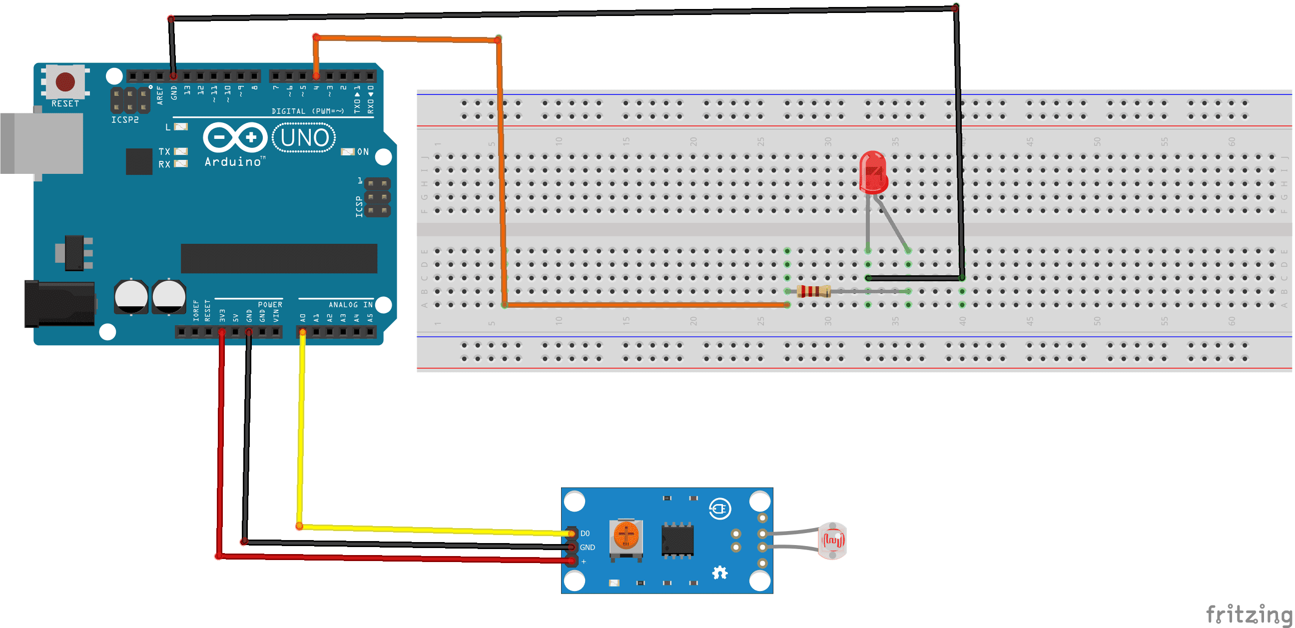
Mounting
To make the assembly, we can connect:
- Red LED terminal (+) to Arduino pin 4
- red LED terminal (-) to Arduino GND pin
- DO pin of KY-018 sensor to A0 pin of Arduino
- VCC pin of KY-018 sensor to 3.3V pin of Arduino
- GND pin of KY-018 sensor to GND pin of Arduino
Program
The program for the automatic lighting system is as follows:
|
1 2 3 4 5 6 7 8 9 10 11 12 13 14 15 16 17 18 19 20 21 22 |
int digitalPin = 4; int analogPin = A0; // KY-026 analog interface int digitalVal; // digital readings int analogVal; //analog readings void setup() { pinMode(digitalPin, OUTPUT); digitalWrite(digitalPin, LOW); } void loop() { // read the value returned by the light sensor analogVal = analogRead(analogPin); if (analogVal>670){ // when the light sensor detects very low brightness digitalWrite(digitalPin, HIGH); // turn on red LED } else { digitalWrite(digitalPin, LOW); // turn off red LEDs } delay(100); } |
You can also see


0 commentaire
Leave a comment


Recent tutorials


Most viewed tutorials


Most commented tutorials


Scroll to Top