Arduino Project Servo motor
Automatic parking barrier with Arduino
Presentation of Automatic parking barrier
An automatic parking barrier is a system that uses sensors and automated mechanisms to control the opening and closing of a barrier to restrict or allow vehicles to enter or exit a parking lot. These systems can use various technologies such as RFID, Bluetooth, or even a mobile application to grant access to authorized vehicles.
An automatic parking barrier system typically includes a barrier arm, a control unit, and various sensors. The barrier arm is the physical barrier that blocks or allows vehicles to enter or exit the parking lot. The control unit is responsible for processing the input from the sensors and deciding whether to open or close the barrier arm. The sensors can include things like RFID readers, which read the information on an RFID tag on a vehicle, or cameras, which can detect the license plate of a vehicle.
To create an automatic parking barrier system using App Inventor, you would need to use a microcontroller such as an Arduino or a Raspberry Pi to control the physical barrier and interface with the sensors. You would then need to create a mobile application using App Inventor that can communicate with the microcontroller and send commands to open or close the barrier arm.
The mobile application would need to include a user interface that allows users to enter their information, such as their RFID tag number or license plate number, and send it to the microcontroller for verification. The microcontroller would then compare the information received with a database of authorized vehicles and decide whether to open or close the barrier arm.
It’s important to note that creating an automatic parking barrier system would require advanced knowledge in electronics, microcontroller programming and communication protocols between the microcontroller and the mobile application. Additionally, the system would require careful planning and design to ensure safety and security of the parking area.
Purpose of this project:
An automatic parking barrier system with Arduino is a system that uses an Arduino microcontroller to control the opening and closing of a barrier to restrict or allow vehicles to enter or exit a parking lot. The Arduino is a low-cost, open-source microcontroller that can be programmed to interact with various sensors and actuators to control the barrier arm.
To create an automatic parking barrier system with Arduino, you would first need to connect the barrier arm to the Arduino using a motorservo. The motor servo controls the power supplied to the barrier arm’s motor, and allows the Arduino to control the movement of the barrier arm.
Next, you would need to connect Two HC-SR04 sensors to the Arduino. These sensors can detect the presence of a vehicle and determine if the barrier should be opened or closed.
You would then need to write a program for the Arduino using the Arduino programming language. This program would be responsible for processing the input from the sensors and deciding whether to open or close the barrier arm.
Finally, you may also want to include a an RGB LED to give a visual indication of the barrier arm status (open/close).
It’s important to note that creating an automatic parking barrier system with Arduino would require advanced knowledge in electronics and microcontroller programming, as well as proper planning and design to ensure safety and security of the parking area. Additionally, the system would require regular maintenance and updates to ensure it continues to function correctly.
In this project we will simulate an automated parking barrier with Arduino. This model resumes the general operation of automated systems that allow access to public parks that can be found in stations, airports, cinemas, supermarkets, etc.
Our barrier opens with a servo motor when the HC-sound sensorSR04 detects a vehicle and closes automatically if not.
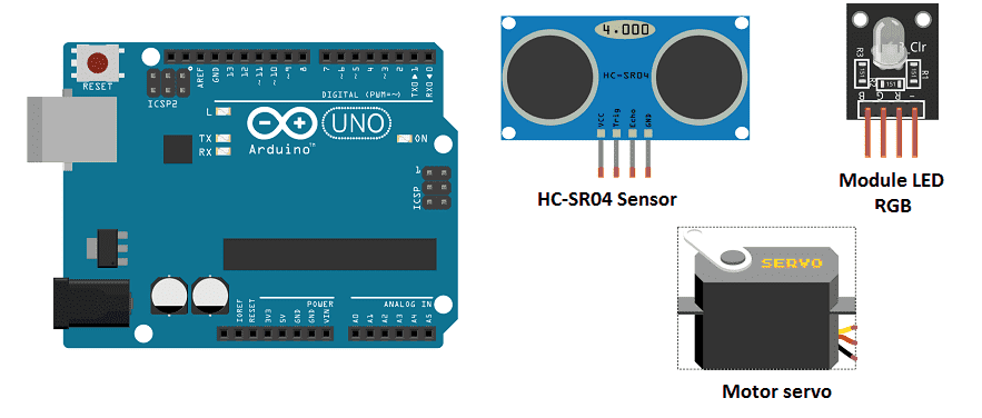
Necessary components
Arduino UNO
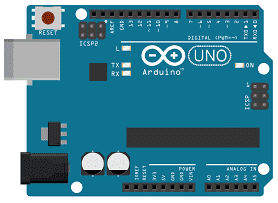
The Arduino UNO is a microcontroller board based on the ATmega328P. It has 14 digital input/output pins, 6 analog inputs, a 16 MHz quartz crystal, a USB connection, a power jack, an ICSP header, and a reset button. It is the most popular and widely used board among the Arduino boards.
The Arduino UNO can be programmed using the Arduino programming language, which is based on C++. It uses a simple and intuitive programming environment, making it easy for beginners to get started with microcontroller programming.
The Arduino UNO can be connected to various sensors and actuators to control different devices and perform different tasks. For example, it can be used to control motors, read data from sensors, display information on an LCD screen, and communicate with other devices via serial communication protocols such as I2C and SPI.
The Arduino UNO can also be powered by a USB cable or an external power supply, making it easy to use in a wide range of projects and applications. It’s compatible with a wide range of shields (expansion boards) that adds functionality to the board, such as Ethernet, WiFi, and Bluetooth, and it’s widely supported by a strong and active community, which provides a lot of tutorials, examples and libraries to help users to get the most of the board.
Two HC-SR04 sensor
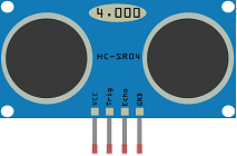
The HC-SR04 sensor is a type of ultrasonic sensor that can be used to measure distance. It can be used in an automatic parking barrier system to detect the presence of a vehicle and determine if the barrier should be opened or closed.
To use the HC-SR04 sensor in a parking barrier system, the sensor would need to be connected to an Arduino microcontroller, which would process the sensor’s output and control the movement of the barrier arm.
The HC-SR04 sensor works by emitting an ultrasonic wave, which bounces off of an object and returns to the sensor. The sensor then measures the time it takes for the wave to return, and calculates the distance to the object based on that time.
In a parking barrier system, the HC-SR04 sensor would be placed at the entrance of the parking lot, facing the incoming vehicles. The sensor would continuously measure the distance to the closest object, and if the distance is less than a certain threshold (indicating the presence of a vehicle), the Arduino would open the barrier arm to allow the vehicle to enter. Once the vehicle has passed, the sensor would detect the absence of an object and the Arduino would close the barrier arm.
It’s worth noting that, the HC-SR04 sensor has a limited range, typically between 2cm and 400cm and can be affected by ambient conditions, such as sunlight or reflections. Additionally, the sensor’s accuracy and resolution may vary, depending on the specific model and the environment, so it’s important to adjust the threshold value accordingly.
Motor servo

A motor servo can be used to control the movement of a barrier arm in an automatic parking barrier system. A motor servo is a type of actuator that can rotate to a specific angle based on a control signal. The control signal is typically a PWM signal sent from a microcontroller such as an Arduino.
To use a motor servo in a parking barrier system, the servo would need to be connected to the Arduino, which would send the control signal to the servo. The servo would then rotate to the specified angle, which in the case of a parking barrier system, would be either fully open or fully closed position.
The barrier arm would need to be mechanically connected to the servo’s output shaft, so that when the servo rotates, it moves the barrier arm. In some cases, you can use a linkage mechanism to convert the rotary motion of the servo into linear motion of the barrier arm.
In a parking barrier system, the Arduino would receive input from sensors such as ultrasonic, infrared, or camera sensors to detect the presence of a vehicle, and based on the input, it would send a control signal to the servo to rotate to the open or close position.
It’s worth noting that, using a motor servo for the barrier arm may require additional hardware such as a motor driver to control the power supply to the servo, and an encoder to provide feedback to the Arduino about the servo’s position. Additionally, the barrier arm should be designed and tested to withstand the wear and tear of the opening and closing process.
RGB LED module
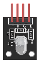
An RGB LED module is a module that contains three LEDs, one red, one green, and one blue. These LEDs can be controlled individually to produce a wide range of colors. RGB LEDs are commonly used in lighting and visual effects applications, such as in automotive lighting, architectural lighting, stage lighting, and electronic devices such as smartphones, laptops, and televisions.
An RGB LED module typically includes three separate connections for the red, green, and blue LEDs, and a common connection, which is typically the cathode (-) of the LEDs. To control the color of the LED, a microcontroller such as an Arduino can be used to adjust the brightness of each LED by sending a PWM signal to the separate connections. By adjusting the brightness of each LED, a wide range of colors can be produced.
To use an RGB LED module with an Arduino, you would need to connect the LEDs to the appropriate pins on the Arduino and write a program to control the brightness of each LED. The program would use the analogWrite() function to set the brightness of each LED, and the delay() function to control the duration of each color.
An RGB LED module can be used in a parking barrier system to provide visual feedback to the users about the status of the barrier. For example, the LED can be set to green when the barrier is open, and red when it is closed.
connecting wires

Connecting wires are used to connect various components in an electronic circuit. They allow for the transfer of electricity, data, or signals between different devices and components.
When connecting wires to an Arduino or other microcontroller, it is important to pay attention to the correct pinout. The pinout refers to the arrangement of pins on the microcontroller and the corresponding function of each pin. The Arduino pinout can be found in the documentation provided by the manufacturer, or in various resources available online.
test plate

A test plate, also known as a test jig, is a device used to test electronic circuits and components. It is a board or plate that has been designed to hold and connect various components and devices in a specific configuration, allowing for the easy testing and measurement of their performance.
A test plate can be used to test various types of electronic circuits and components, such as microcontrollers, sensors, and actuators. It typically includes connectors and sockets for connecting wires, power supply and measurement devices such as multimeters, oscilloscopes, and power supplies.
a arm barrier in the form of a pen
Montage du Parking
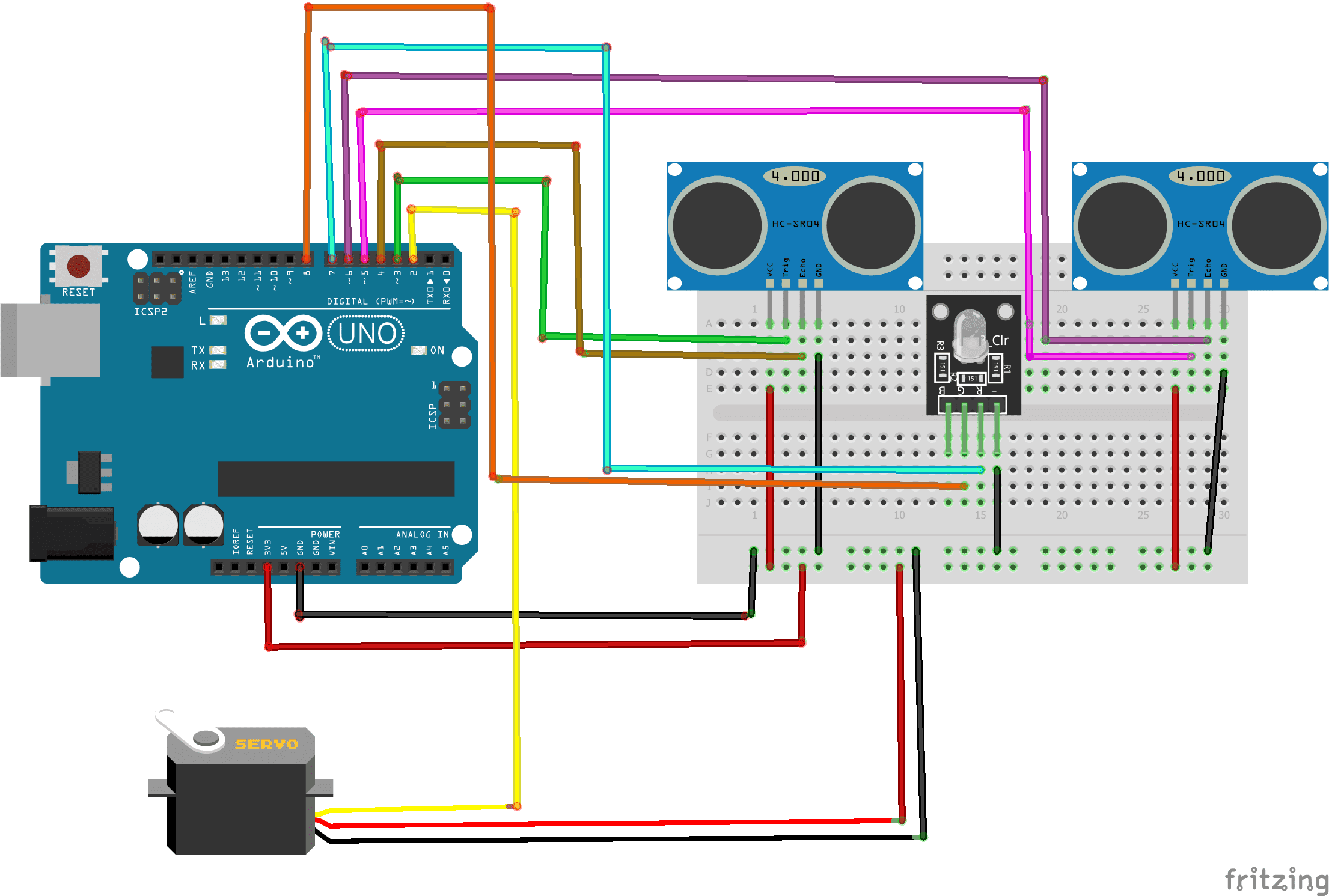
To make the assembly, we can connect:
For first HC-SR04 sensor:
- VCC pin to 3.3V pin of Arduino
- Trig pin to pin 3 of Arduino
- ECHO pin to pin 4 ofArduino
- GND pin to GND pin of Arduino
For second HC-SR04 sensor:
- VCC pin to 3.3V pin of Arduino
- Trig pin to pin 5 of Arduino
- ECHO pin to pin 6 ofArduino
- GND pin to GND pin of Arduino
For motor servo
- red wire: wire of the power supply to be connected to the 5V pin of the Arduino
- brown wire: wire to connect to the GND pin of the Arduino
- Yellow wire: positioning signal wire connected to pin 2 of the Arduino
For Module LED RGB:
- Pin 7 of Arduino to (R) pin of red color of RGB LED module
- Pin 8 of Arduino to (G) pin of green color of RGB LED module
- GND Pin of Arduino to GND pin of RGB LED module
Program
Here is the program for the automated parking system:
|
1 2 3 4 5 6 7 8 9 10 11 12 13 14 15 16 17 18 19 20 21 22 23 24 25 26 27 28 29 30 31 32 33 34 35 36 |
#include <HCSR04.h> #include <Servo.h> Servo monServomoteur; const int servoPin=2; const int trig1Pin = 3; const int echo1Pin = 4; const int trig2Pin = 5; const int echo2Pin = 6; const int LEDrouge=7; const int LEDvert=8; int position = 180; UltraSonicDistanceSensor distanceSensor1(trig1Pin, echo1Pin); UltraSonicDistanceSensor distanceSensor2(trig2Pin, echo2Pin); void setup(){ monServomoteur.attach(servoPin); pinMode(LEDrouge,OUTPUT); pinMode(LEDvert,OUTPUT); } void loop(){ if(((((distanceSensor1.measureDistanceCm()+1)<6)&&(distanceSensor1.measureDistanceCm()+1)>0))||((distanceSensor2.measureDistanceCm()+1<6)&&(distanceSensor2.measureDistanceCm()+1)>0)) {// If one of the two HC-SR04 sensors detects a vehicle monServomoteur.write(90); // the barrier open digitalWrite(LEDrouge,LOW); digitalWrite(LEDvert,HIGH); // The LED lights up in green delay(5000); }else { monServomoteur.write(180); digitalWrite(LEDrouge,HIGH); // The LED lights up in red digitalWrite(LEDvert,LOW); // the barrier closes } delay(100); } |
You can also see

0 commentaire
Leave a comment


Recent tutorials


Most viewed tutorials


Most commented tutorials


Scroll to Top