An obstacle detection system is a technology that can identify and alert drivers to potential obstacles or hazards on the road. These systems use a variety of sensors and cameras to monitor the surrounding environment and provide real-time data to the driver.
There are several types of obstacle detection systems available, including:
- Ultrasonic sensors: These sensors use sound waves to detect objects in the vehicle’s blind spots or around the perimeter of the car.
- Radar sensors: These sensors use radio waves to detect objects in the vehicle’s path and can also detect the speed and distance of other vehicles.
- LIDAR sensors: These sensors use laser technology to create a 3D map of the surrounding environment, allowing for more precise obstacle detection.
- Cameras: These can be used to provide visual information to the driver about the surrounding environment, including other vehicles, pedestrians, and obstacles.
Obstacle detection systems are becoming increasingly common in modern vehicles, and they can help prevent accidents by alerting drivers to potential hazards that they may not have seen otherwise.
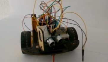
Objective of this project:
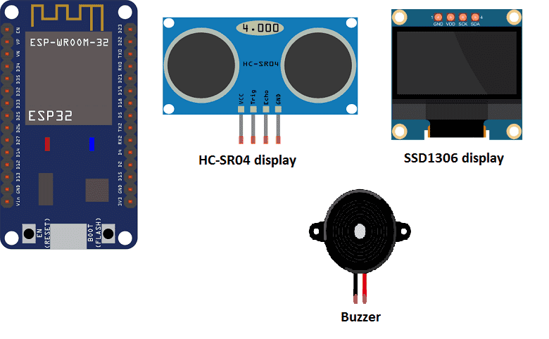
In this project we will realize an obstacle detection system with Arduino. This system mainly uses an ultrasonic sensor, buzzer and LED.
When the ultrasonic sensor detects an obstacle at a distance <4cm, the ESP32 board gives the order for the buzzer to sound.
Necessary components
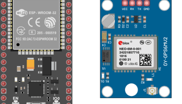
ESP32
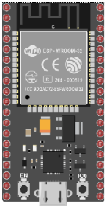
The ESP32 is a low-cost, low-power, and high-performance microcontroller designed by Espressif Systems. It is based on the Tensilica Xtensa LX6 dual-core processor and features built-in Wi-Fi and Bluetooth connectivity, making it popular for a wide range of IoT projects.
The ESP32 microcontroller comes in a variety of development boards that are designed to make it easy to prototype and develop projects. Some popular ESP32 development boards include:
- ESP32 DevKitC: This is the official development board for the ESP32 and features a USB interface, onboard LED, and all the necessary pins broken out for easy prototyping.
- NodeMCU-32S: This is another popular ESP32 development board that features onboard Wi-Fi and USB connectivity, making it easy to connect to a computer or network.
- ESP-WROVER-KIT: This development board features an integrated TFT display, camera interface, and microSD card slot, making it ideal for developing projects that require these features.
- ESP32-PICO-KIT: This is a small development board that features an onboard USB interface, LED, and reset button, making it easy to prototype and develop small projects.
- ESP32-WROOM-32D: This is an ESP32 module that features an onboard antenna and all the necessary pins broken out for easy prototyping.
ultrasonic sensor (HC-SR04)
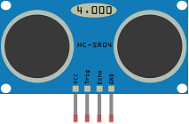
The HC-SR04 is an ultrasonic distance sensor. It uses sound waves to measure the distance to an object. The sensor sends out a 40kHz sound wave, and then measures the time it takes for the sound wave to bounce back to the sensor. By measuring the time it takes for the sound wave to travel to an object and back, the HC-SR04 can calculate the distance to that object. It is commonly used in robotics, automation and other projects where distance measurement is required.
Buzzer
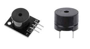
A buzzer is an electronic device that produces a sound when an alternating current is applied to it. It is used for a variety of purposes, such as in alarms, timers, and other devices that need to produce an audible signal.
SSD1306 display
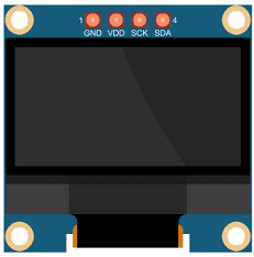
The SSD1306 display is a popular type of OLED display that is commonly used in small electronic projects. The display is typically driven by a microcontroller like an Arduino, ESP32, or Raspberry Pi.
connecting wires

Connecting wires are used to connect various components in an electronic circuit. They allow for the transfer of electricity, data, or signals between different devices and components.
When connecting wires to an Arduino or other microcontroller, it is important to pay attention to the correct pinout. The pinout refers to the arrangement of pins on the microcontroller and the corresponding function of each pin. The Arduino pinout can be found in the documentation provided by the manufacturer, or in various resources available online.
test plate

A test plate, also known as a test jig, is a device used to test electronic circuits and components. It is a board or plate that has been designed to hold and connect various components and devices in a specific configuration, allowing for the easy testing and measurement of their performance.
A test plate can be used to test various types of electronic circuits and components, such as microcontrollers, sensors, and actuators. It typically includes connectors and sockets for connecting wires, power supply and measurement devices such as multimeters, oscilloscopes, and power supplies.
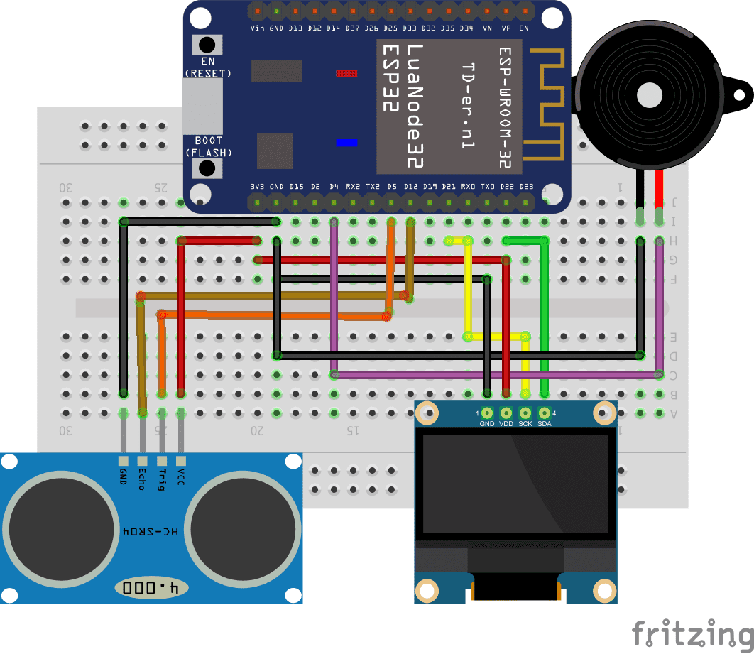
Mounting:
To perform the assembly, you can connect
For buzzer:
-
the terminals (+) to pin D4 of the ESP32 board
-
the terminals (-) to the GND pin of the ESP32 board
For HC-SR04 sensor:
-
the TRIG pin to pin D5 of the ESP32 board
-
the Echo pin to pin D18 of the ESP32 board
-
the VCC pin to the VCC pin of the ESP32 board
-
the GND pin to the GND pin of the ESP32 board
For display:
-
the SCL pin to pin D22 of the ESP32 board
-
the VCC pin to the 3.3V pin of the ESP32 board
-
the GND pin to the GND pin of the ESP32 board
-
the SDA pin the D21 pin of the ESP32 card
Micropython program
Here is the program of the sound alarm system:
|
1 2 3 4 5 6 7 8 9 10 11 12 13 14 15 16 17 18 19 20 |
from hcsr04 import HCSR04 from machine import Pin,I2C import ssd1306,time i2c = I2C(scl=Pin(22), sda=Pin(21)) #Init i2c oled=ssd1306.SSD1306_I2C(128,64,i2c,0x3c) buzzer=Pin(4,Pin.OUT) sensor = HCSR04(trigger_pin=5,echo_pin=18,echo_timeout_us=1000000) while True: distance = sensor.distance_cm() print(distance,' cm') time.sleep_ms(100) oled.fill(0) oled.text("Distance:",30,20) oled.text(str(distance),30,40) oled.text("cm",30,50) oled.show() #display the distance between the sensor and the object if (distance<4): buzzer.value(1) # buzzer sounds else: buzzer.value(0) #buzzer stops ringing |
Note: you must import the following two libraries: hcsr04 and ssd1306
You can also see

0 commentaire
Leave a comment


Recent tutorials


Most viewed tutorials


Most commented tutorials


Scroll to Top