Purpose of this tutorial:
Blinking two LEDs with an Arduino is a simple task that can be accomplished using the digital output pins of the Arduino. The following steps can be used to blink two LEDs using an Arduino:
- Connect the positive leg of the first LED to a digital output pin of the Arduino.
- Connect the negative leg of the first LED to a resistor and then connect the other end of the resistor to the GND pin of the Arduino.
- Connect the positive leg of the second LED to a different digital output pin of the Arduino.
- Connect the negative leg of the second LED to a resistor and then connect the other end of the resistor to the GND pin of the Arduino.
- Open the Arduino IDE and write a program that uses the digitalWrite() function to control the state of the digital output pins.
- The program should use a loop structure to repeatedly turn the LEDs on and off with a delay in between.
- Once the code is written, upload the program to the Arduino board.
The above steps will blink the two LEDs alternatively, the delay function can be used to control the blinking rate.
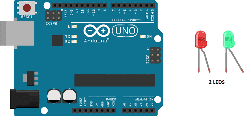
In this tutorial we will flash two LEDs (red and green) with the Arduino board every two seconds.
Necessary components
Arduino UNO
The Arduino UNO is a microcontroller board based on the ATmega328P. It has 14 digital input/output pins, 6 analog inputs, a 16 MHz quartz crystal, a USB connection, a power jack, an ICSP header, and a reset button. It is the most popular and widely used board among the Arduino boards.
The Arduino UNO can be programmed using the Arduino programming language, which is based on C++. It uses a simple and intuitive programming environment, making it easy for beginners to get started with microcontroller programming.
The Arduino UNO can be connected to various sensors and actuators to control different devices and perform different tasks. For example, it can be used to control motors, read data from sensors, display information on an LCD screen, and communicate with other devices via serial communication protocols such as I2C and SPI.
The Arduino UNO can also be powered by a USB cable or an external power supply, making it easy to use in a wide range of projects and applications. It’s compatible with a wide range of shields (expansion boards) that adds functionality to the board, such as Ethernet, WiFi, and Bluetooth, and it’s widely supported by a strong and active community, which provides a lot of tutorials, examples and libraries to help users to get the most of the board.
2 LEDs
An LED (Light Emitting Diode) is a semiconductor device that emits light when an electric current is passed through it. LEDs are widely used in a variety of applications because they are energy-efficient, have a long lifespan, and are available in a wide range of colors.
LEDs can be found in many electronic devices such as televisions, smartphones, computers, and traffic lights. They are also used in automotive lighting, general illumination, and as indicator lights.
220 ohm resistors

Resistors are passive electronic components that are used to control the flow of electric current in a circuit. They are typically made of a conductive material, such as carbon or metal, that resists the flow of electricity. The resistance of a resistor is measured in ohms (Ω). Resistors can be used to divide voltage, limit current, and bias active devices. They are widely used in electronic circuits for a wide range of applications.
connecting wires

Connecting wires are used to connect various components in an electronic circuit. They allow for the transfer of electricity, data, or signals between different devices and components.
When connecting wires to an Arduino or other microcontroller, it is important to pay attention to the correct pinout. The pinout refers to the arrangement of pins on the microcontroller and the corresponding function of each pin. The Arduino pinout can be found in the documentation provided by the manufacturer, or in various resources available online.
test plate

A test plate, also known as a test jig, is a device used to test electronic circuits and components. It is a board or plate that has been designed to hold and connect various components and devices in a specific configuration, allowing for the easy testing and measurement of their performance.
A test plate can be used to test various types of electronic circuits and components, such as microcontrollers, sensors, and actuators. It typically includes connectors and sockets for connecting wires, power supply and measurement devices such as multimeters, oscilloscopes, and power supplies.
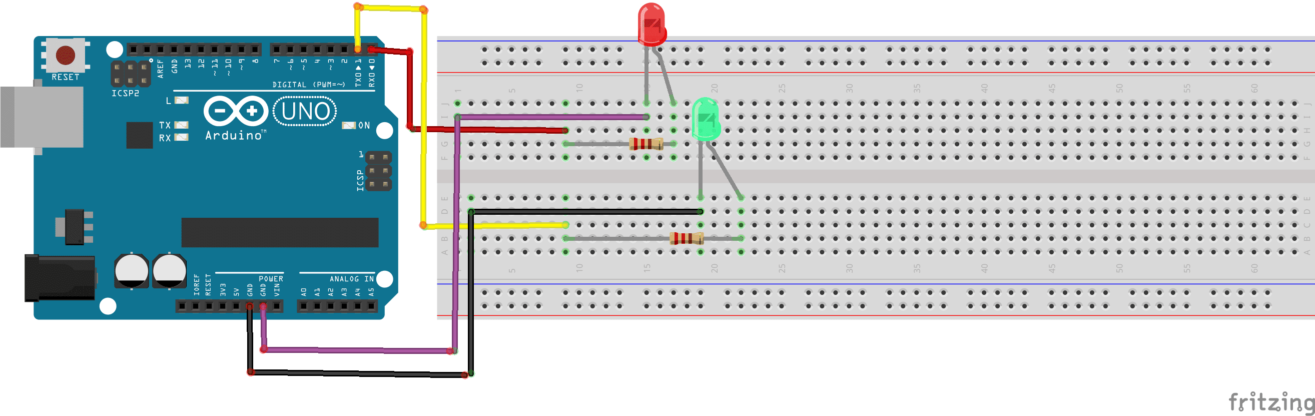
Mounting
For the electronic assembly, we will need an Arduino Uno card, two LEDs, two resistors, a breadboard. This assembly will be connected to a computer via a USB cable for the power supply (5 Volts) and the transfer of the program to be installed on the microcontroller of the Arduino Uno board.
To achieve this assembly:
First We Connect the digital pin 0 of the Arduino board to the resistance leg.
Secondly,we connect the second anode resistance leg (terminal +) of the red LED.
Third we connect the red LED cathode (terminal -) to the Arduino GND.
Fourth we connect also the digital pin 1 of the Arduino board to the second resistor leg.
Then we connect the second anode resistance leg (terminal +) of the green LED.
Finally, the green LED cathode (terminal -) is connected to the Arduino GND.
Program Arduino
Here is the program that allows to flash 2 LEDs.
|
1 2 3 4 5 6 7 8 9 10 11 12 13 |
void setup(){ pinMode(0,OUTPUT); //sets the number 0 digital pin of the Arduino in output mode pinMode(1,OUTPUT); //sets the number 1 digital pin of the Arduino in output mode } void loop(){ digitalWrite(0,HIGH); //red LED lights up digitalWrite(1,LOW); //green LED goes out delay(2000); digitalWrite(0,LOW); //red LED goes out digitalWrite(1,HIGH); //green LED lights up delay(2000); } |
Every Arduino program has 2 main functions, setup() and loop() that need to be declared.
Let’s pass the setup() function, which is only performed once during the program: when the Arduino starts. Here we will define the role of the pins: input or output. The function is called pinMode(). The pins connected to the LEDs are outputs.
The loop() function loops continuously after the execution of the setup() function.
In the loop() function:
digitalWrite(0,LOW) sets a logic 0 (LOW) level on the red LED pin which will turn off.
digitalWrite(1,HIGH) sets a logic 1 (HIGH) level on the green LED pin which will light up.
digitalWrite(0,HIGH) sets a logic 0 (LOW) level on the red LED pin which will turn up.
digitalWrite(1,LOW) sets a logic 1 (HIGH) level on the green LED pin which will light off.
You can also see

0 commentaire
Leave a comment


Recent tutorials


Most viewed tutorials


Most commented tutorials


Scroll to Top