Representation a remote control car by Joystick with Micro:bit
A robot car, also known as an autonomous car or self-driving car, is a vehicle that is capable of sensing its environment and navigating without human input. These cars use a combination of sensors, such as cameras, lidar, radar, and ultrasonic sensors, to collect data about their surroundings. This data is then processed by onboard computers and algorithms, which determine the car’s next actions, such as braking, accelerating, and steering.
Robot cars are designed to improve transportation efficiency, reduce human error, and increase safety on the roads. They can be used for a variety of applications, such as personal transportation, ride-sharing, logistics, and even delivery. Companies such as Waymo, Tesla and Uber are working on developing autonomous cars.
A remote control robot car can be built using a Micro:bit and a joystick. The Micro:bit can be programmed to receive input from the joystick and control the motors of the robot car accordingly.
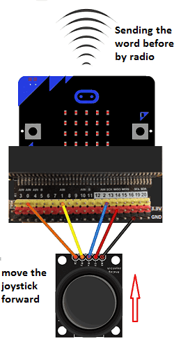
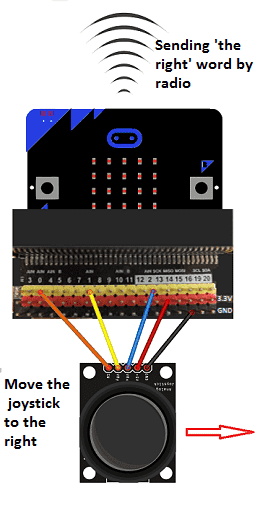
The joystick is typically connected to the Micro:bit using a breakout board, which allows the Micro:bit to read the position of the joystick’s potentiometers. The Micro:bit can then be programmed to interpret the joystick‘s position and send control signals to the robot car‘s motors. For example, when the joystick is pushed forward, the Micro:bit can send a signal to the robot car‘s motors to move forward. When the joystick is pulled back, the Micro:bit can send a signal to the motors to move in reverse.
Additionally, the Micro:bit can also be programmed to interpret the button inputs from the joystick and perform specific actions. For example, when a button is pressed, the Micro:bit can send a signal to the robot car‘s motors to stop or to perform a specific action, such as activating an LED or playing a sound.
Purpose of this project:
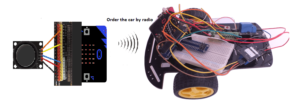
A remote control robot car can also be built using a Micro:bit and a joystick, but controlled wirelessly using radio communication. The Micro:bit can be programmed as a transmitter, sending control signals wirelessly to the robot car’s Micro:bit, which acts as a receiver.
The joystick is typically connected to the transmitter Micro:bit using a breakout board, which allows the Micro:bit to read the position of the joystick‘s potentiometers. The transmitter Micro:bit can then be programmed to interpret the joystick’s position and send control signals wirelessly to the robot car’s Micro:bit using the radio module.
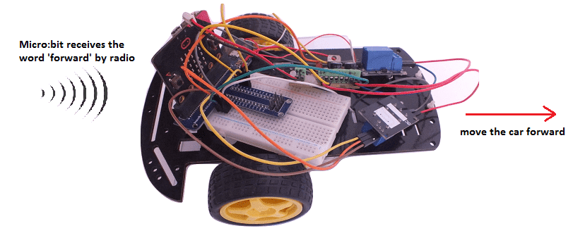
The receiver Micro:bit, on the robot car, can then be programmed to receive the control signals and control the motors of the robot car accordingly. For example, when the joystick is pushed forward on the transmitter, the receiver Micro:bit can send a signal to the robot car‘s motors to move forward. When the joystick is pulled back, the receiver Micro:bit can send a signal to the motors to move in reverse.
This method allows the operator to control the robot car from a distance, as long as the radio signal can reach the robot car. It is important to note that radio communication requires proper configuration of the radio modules, including the channel and the data rate, to avoid interference and ensure reliable communication.
In this project we will build a remotely controlled car (by radio) controllable by two Micro:bit cards.
The user will be able to drive the car by a joystick controller in three directions (front, right and left) and stop it.
Required components
two Micro:bit boards
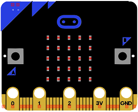
Micro:bit is a small, low-cost microcontroller board that was developed by the Micro:bit Educational Foundation for use in computer education. It is designed to be easy to use and accessible to a wide range of users, including children and beginners. The Micro:bit board measures about 4cm by 5cm and features a 25-pin edge connector, a 5×5 LED matrix, two programmable buttons, an accelerometer, a compass, a Bluetooth Low Energy (BLE) module, and a USB connector.
The Micro:bit is programmed using a variety of programming languages such as Python, JavaScript, and Microsoft Block Editor. It can be used to control a wide range of devices and projects, including robots, drones, lights, and more. The board can be powered by a USB cable or a 3V coin cell battery and can be programmed using a computer or mobile device.
The Micro:bit is widely used in education, providing a hands-on learning experience for students of all ages to learn computer programming, logic, and problem-solving. It’s also used by hobbyist and makers to create fun and interactive projects.
two GPIO boards
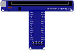
A Micro:bit GPIO (General Purpose Input/Output) Expansion Board is an accessory that can be used to extend the capabilities of a Micro:bit by providing additional input/output (I/O) pins. These pins can be used to connect sensors and actuators, such as LEDs, buttons, motors, and other electronic components.
The expansion board typically connects to the Micro:bit using a standard edge connector and provides a set of male headers that can be used to connect external components.
Joystisck
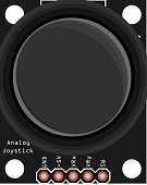
A joystick is a type of input device that typically consists of a stick or handle that can be moved in different directions. The movement of the joystick is often converted into electrical signals that can be interpreted by a computer or microcontroller, such as a Micro:bit.
There are several types of joysticks available, each with their own set of features and capabilities. Some common types include:
- Analog joysticks: These joysticks use potentiometers to measure the position of the stick and convert it into an electrical signal. The signal can be read by a microcontroller, such as a Micro:bit, to determine the direction and amount of movement of the joystick.
- Digital joysticks: These joysticks use switches to detect the direction of movement of the stick. They can provide only a limited number of directions, unlike analog joystick.
- Joystick modules: These are ready-made joystick modules that come with a built-in potentiometer or switch and can be easily connected to a Micro:bit or other microcontroller using a breakout board.
Joysticks are commonly used in video game controllers, remote control devices, and other applications where precise control is needed. They can be used in a combination of other sensors to control a robot or other devices.
two relay
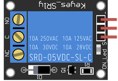
In a robot car, relays are used to control the motors that drive the wheels of the car. A relay is an electronic switch that is controlled by a low-voltage input signal, and it is used to turn the motors on and off. The relay typically consists of an electromagnet, a switch, and a set of contacts. The electromagnet is activated by the low-voltage input signal, which causes the switch to close or open the contacts, allowing or cutting off power to the motors.
When the relay receives a signal from the microcontroller to move forward, for example, it will close the contacts to the motor, allowing power to flow to the motor, and the car will move forward. When the signal to stop is received, the relay will open the contacts, cutting off power to the motor, and the car will stop. This allows for the motors to be controlled remotely or by a microcontroller, such as Micro:bit.
A robot car may have multiple relays, one for each motor or one for each set of motors (front and back or left and right). Relays can also be used to control other electronic devices in the robot car such as lights, sensors or cameras.
2 wheel car robot kit
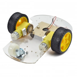
A 2-wheel car robot kit is a collection of components that can be used to build a small, autonomous robot that moves on two wheels. These kits typically include a microcontroller, such as a ESP32 card, to control the robot’s movements, as well as motors, wheels, and other hardware to enable the robot to move and navigate.
2-wheel car robots are often used as educational tools, as they can be used to teach basic principles of robotics, electronics, and programming. They can also be used as a platform for experimenting with different control algorithms, sensors, and other hardware.
This robot kit is composed of:
-
car chassis.
-
2 gear motors (1:48)
-
2 car tires
-
1 universal wheel
9V battery
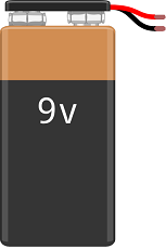
A 9V battery is a type of primary cell battery that is commonly used in small electronic devices such as remote controls, smoke detectors, and portable radios. It is known for its compact size and relatively high voltage output. The 9V battery is also known as a “transistor battery” because it was originally designed for use in portable transistor radios.
connecting wires

Connecting wires are used to connect various components in an electronic circuit. They allow for the transfer of electricity, data, or signals between different devices and components.
When connecting wires to an Arduino or other microcontroller, it is important to pay attention to the correct pinout. The pinout refers to the arrangement of pins on the microcontroller and the corresponding function of each pin. The Arduino pinout can be found in the documentation provided by the manufacturer, or in various resources available online.
test plate

A test plate, also known as a test jig, is a device used to test electronic circuits and components. It is a board or plate that has been designed to hold and connect various components and devices in a specific configuration, allowing for the easy testing and measurement of their performance.
A test plate can be used to test various types of electronic circuits and components, such as microcontrollers, sensors, and actuators. It typically includes connectors and sockets for connecting wires, power supply and measurement devices such as multimeters, oscilloscopes, and power supplies.
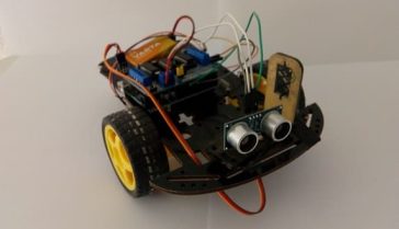
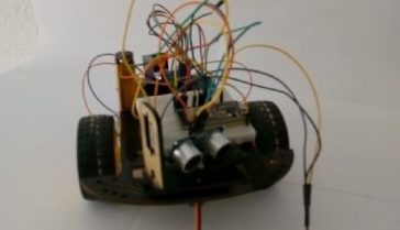
construction of the car
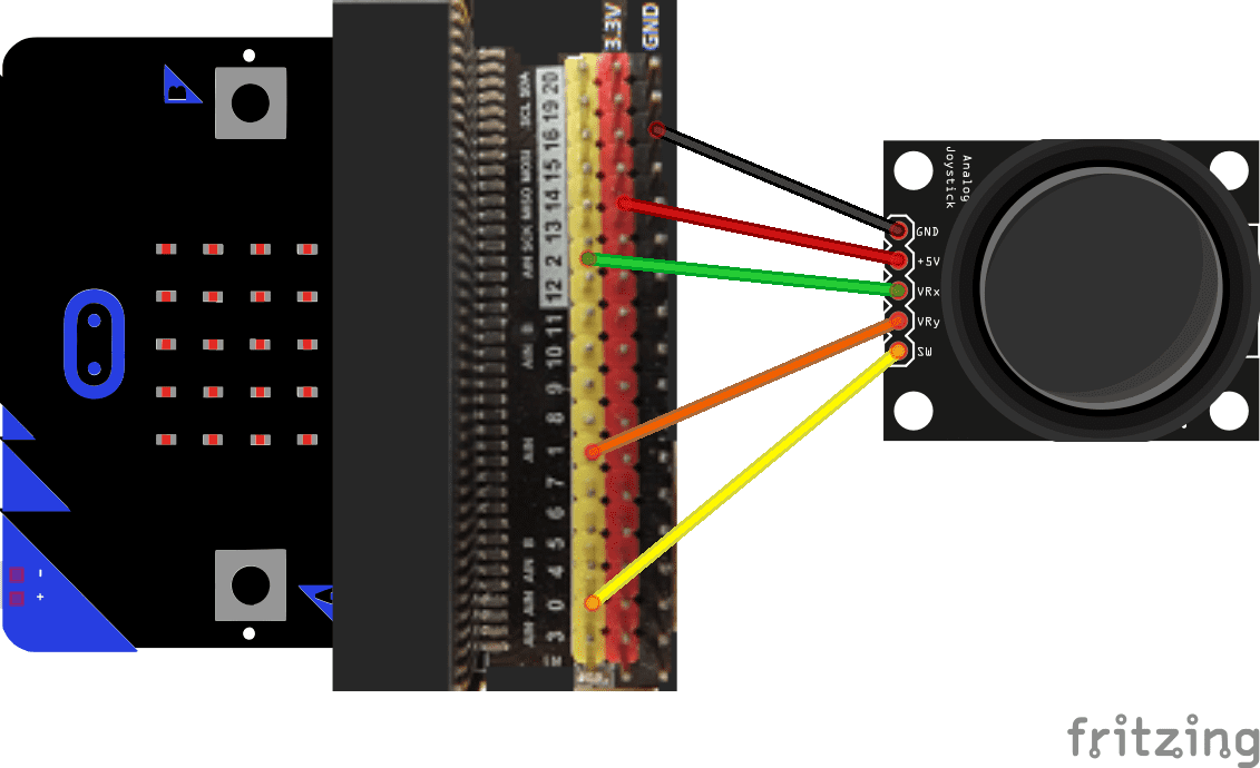
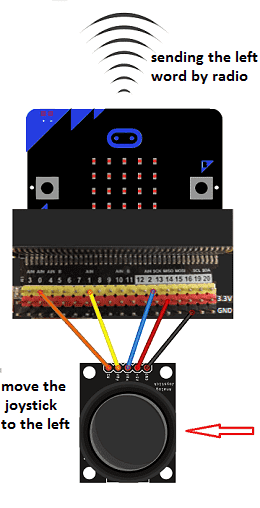
Mounting the joystick joystick with Micro:bit
You can connect:
- The +5V pin of the 3.3V joystick of the micro:bit
- The GND pin of the joystick to the GND of the micro:bit
- The VRx pin of the joystick to the pin P2 of the micro:bit
- VRy pin from joystick to pin P1 from micro:bit
- Pin SW from joystick to pin P0 from micro:bit
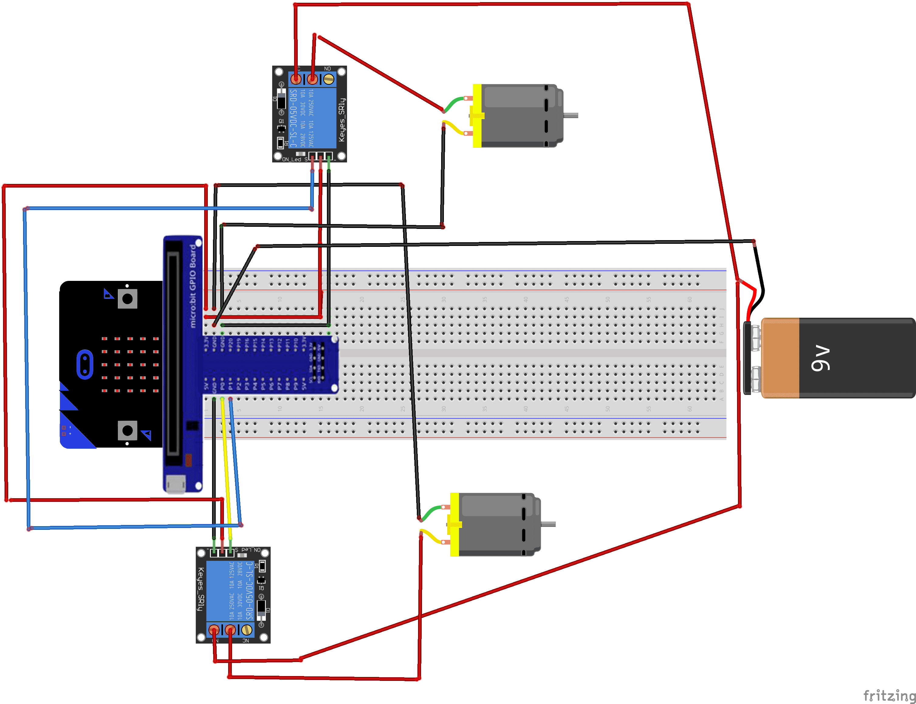
Assembling the car with Micro:bit
To make the assembling, one can connect
For the first relay:
- pin S to pin P0 of the Micro:bit board
- the pin (+) to pin 3.3V of the Micro:bit board
- the pin (-) to the GND of the Micro:bit board
- the pin ON to an energy of 5V
For the second relay:
- pin S to pin P1 of the Micro:bit board
- pin (+) to pin 3.3V of the Micro:bit board
- pin (-) to the GND of the Micro:bit board
- pin ON to an energy of 5V
For each of the two motors:
- the first terminal to the COM pin of the relay
- the second terminal to the GND terminal of the Micro:bit board
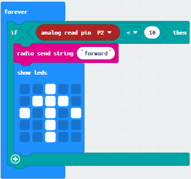
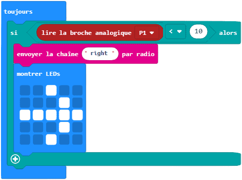
First makecode program
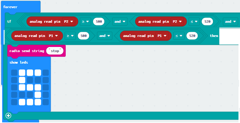
Here is the makecode program for the micro:bit card connected to the joystick controller:
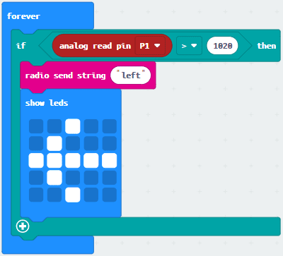
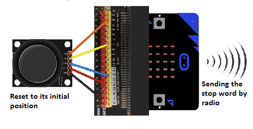
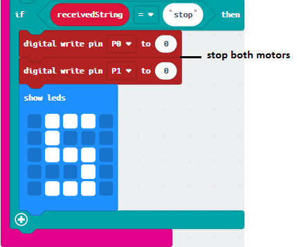
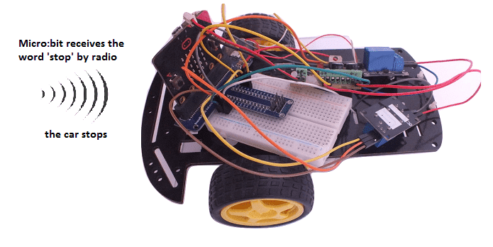
When the joystick returns to its initial position (neutral): The 2 pins P1 and P2 of the micro:bit return values between 500 and 520 and the micro:bit board radio sends the word ‘stop’ to the Maqueen micro:bit board.
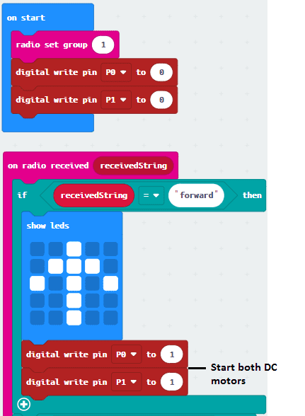
Second Makecode program
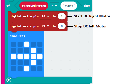
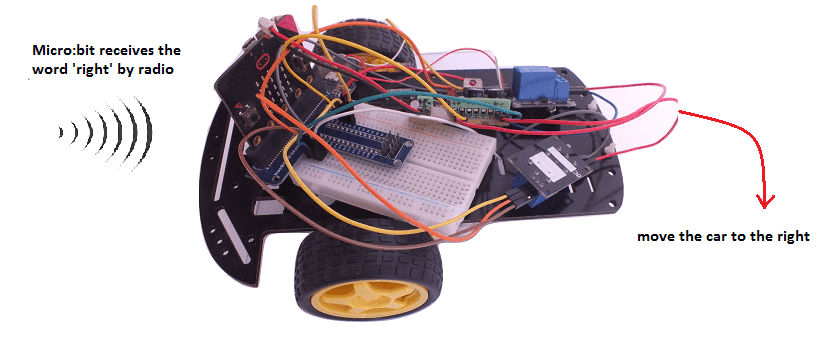
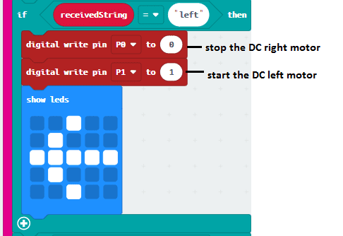
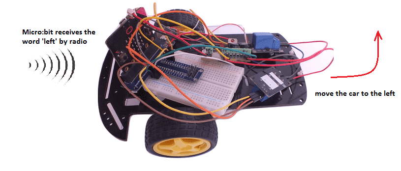
Here is the makecode program for the micro:bit card connected to the car.
You can also see

0 commentaire
Leave a comment


Recent tutorials


Most viewed tutorials


Most commented tutorials


Scroll to Top