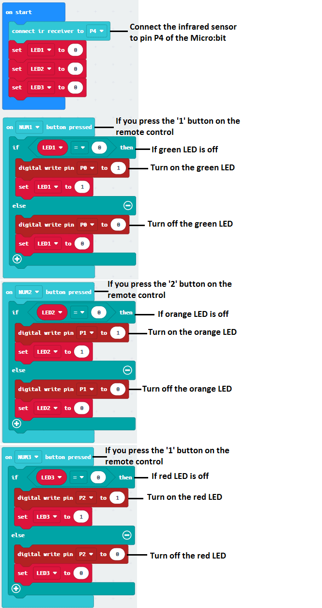
To control LEDs with a Micro:bit using an infrared remote control, you will need to use an infrared receiver module and a Micro:bit.
- First, you will need to connect the infrared receiver module to the Micro:bit‘s pins and write a program to read the signals from the remote control.
- Next, you will need to connect the LEDs to the Micro:bit‘s pins and write a program to control the LEDs based on the signals received from the remote control.
- You will then need to write a program that runs on the Micro:bit to receive the infrared signals from the remote control and interpret the signals.
- The micro:bit can interpret the signals and control the LEDs based on the button pressed on the remote control.
Note: The details of the implementation can vary depending on the specific infrared receiver module and the programming language you are using. It is important to check the documentation of the infrared receiver module and the Micro:bit to understand the specific pin connections and commands required for the implementation.
Purpose of this project:
In this project we will remotely turn on LEDs by an infrared remote control:
- If you press the button 1 on the remote control, the green LED will turn on or off.
- If you press button 2 on the remote control, the orange LED will turn on or off.
- If you press the 3 button on the remote control, the red LED will turn on or off.
Necessary components
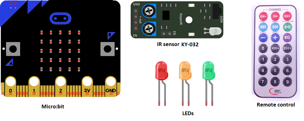
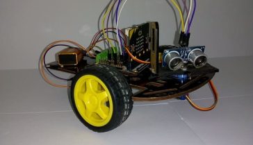
Micro:bit
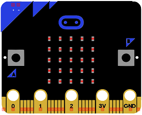
Micro:bit is a small, programmable computer developed by the BBC in the United Kingdom. It is designed to be easy to use and accessible to students and beginners, and can be used to learn coding and computer science concepts. The device features a 5×5 LED matrix, two programmable buttons, a built-in accelerometer and magnetometer, and a variety of input/output (I/O) pins for connecting sensors and actuators.
The Micro:bit can be programmed using a variety of programming languages including Python, JavaScript, and Microsoft Block Editor. It also has a built-in Bluetooth module, which can be used to connect to other devices such as smartphones or other Micro:bits for wireless communication.
The Micro:bit is widely used in educational settings as a tool for teaching coding and computer science, but it can also be used for a variety of projects and applications such as building robots, creating interactive games, and controlling devices via Bluetooth.
Micro:bit GPIO Expansion Board
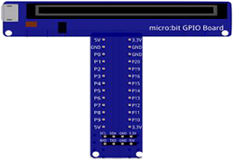
A Micro:bit GPIO (General Purpose Input/Output) Expansion Board is an accessory that can be used to extend the capabilities of a Micro:bit by providing additional input/output (I/O) pins. These pins can be used to connect sensors and actuators, such as LEDs, buttons, motors, and other electronic components.
The expansion board typically connects to the Micro:bit using a standard edge connector and provides a set of male headers that can be used to connect external components.
The Micro:bit GPIO Expansion Board can provide additional functionality to the Micro:bit such as:
- More pins to connect sensors or actuators
- Additional power supply options
- Additional communication interfaces such as I2C or SPI
- Protection to the Micro:bit and the connected components
Red LED- Yellow LED – Green LED
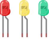
An LED (Light Emitting Diode) is a semiconductor device that emits light when an electric current is passed through it. LEDs are widely used in a variety of applications because they are energy-efficient, have a long lifespan, and are available in a wide range of colors.
LEDs can be found in many electronic devices such as televisions, smartphones, computers, and traffic lights. They are also used in automotive lighting, general illumination, and as indicator lights.
Ky-032 infrared sensor
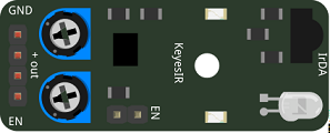
The KY-032 infrared sensor module is a common infrared sensor that can be used to detect obstacles or other infrared-emitting sources. It is based on the infrared reflection principle, which means that it can detect objects by measuring the reflection of infrared light emitted by the sensor.
The module typically includes an infrared transmitter and an infrared receiver, which are used to emit and detect infrared light, respectively. It also includes a potentiometer that can be used to adjust the sensitivity of the sensor.
The module typically has four pins: VCC, GND, OUT, and ADJ. The VCC and GND pins are used to provide power to the module, while the OUT pin is used to output a digital signal indicating the presence or absence of an obstacle. The ADJ pin is used to adjust the sensitivity of the sensor.
The KY-032 infrared sensor can be used with a microcontroller, such as the Micro:bit, to detect obstacles and trigger actions based on the presence or absence of an obstacle. It can be used in a variety of projects, such as obstacle detection in robots, motion detection in security systems, and automatic door openers.
infrared remote control
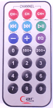
An infrared remote control is a device that uses infrared (IR) signals to remotely control other devices. These signals are transmitted via infrared light, which is invisible to the human eye. The remote control typically includes a set of buttons, each of which corresponds to a specific command or function. When a button is pressed, the remote control sends an IR signal that can be received by the controlled device.
An IR remote control typically includes a small IR LED that emits the infrared signals. These signals are typically encoded with a specific protocol, such as the NEC protocol, Sony SIRC protocol or RC-5 protocol, which allows the controlled device to distinguish the signals from other IR sources and interpret the commands.
connecting wires

Connecting wires are used to connect various components in an electronic circuit. They allow for the transfer of electricity, data, or signals between different devices and components.
When connecting wires to an Arduino or other microcontroller, it is important to pay attention to the correct pinout. The pinout refers to the arrangement of pins on the microcontroller and the corresponding function of each pin. The Arduino pinout can be found in the documentation provided by the manufacturer, or in various resources available online.
test plate

A test plate, also known as a test jig, is a device used to test electronic circuits and components. It is a board or plate that has been designed to hold and connect various components and devices in a specific configuration, allowing for the easy testing and measurement of their performance.
A test plate can be used to test various types of electronic circuits and components, such as microcontrollers, sensors, and actuators. It typically includes connectors and sockets for connecting wires, power supply and measurement devices such as multimeters, oscilloscopes, and power supplies.
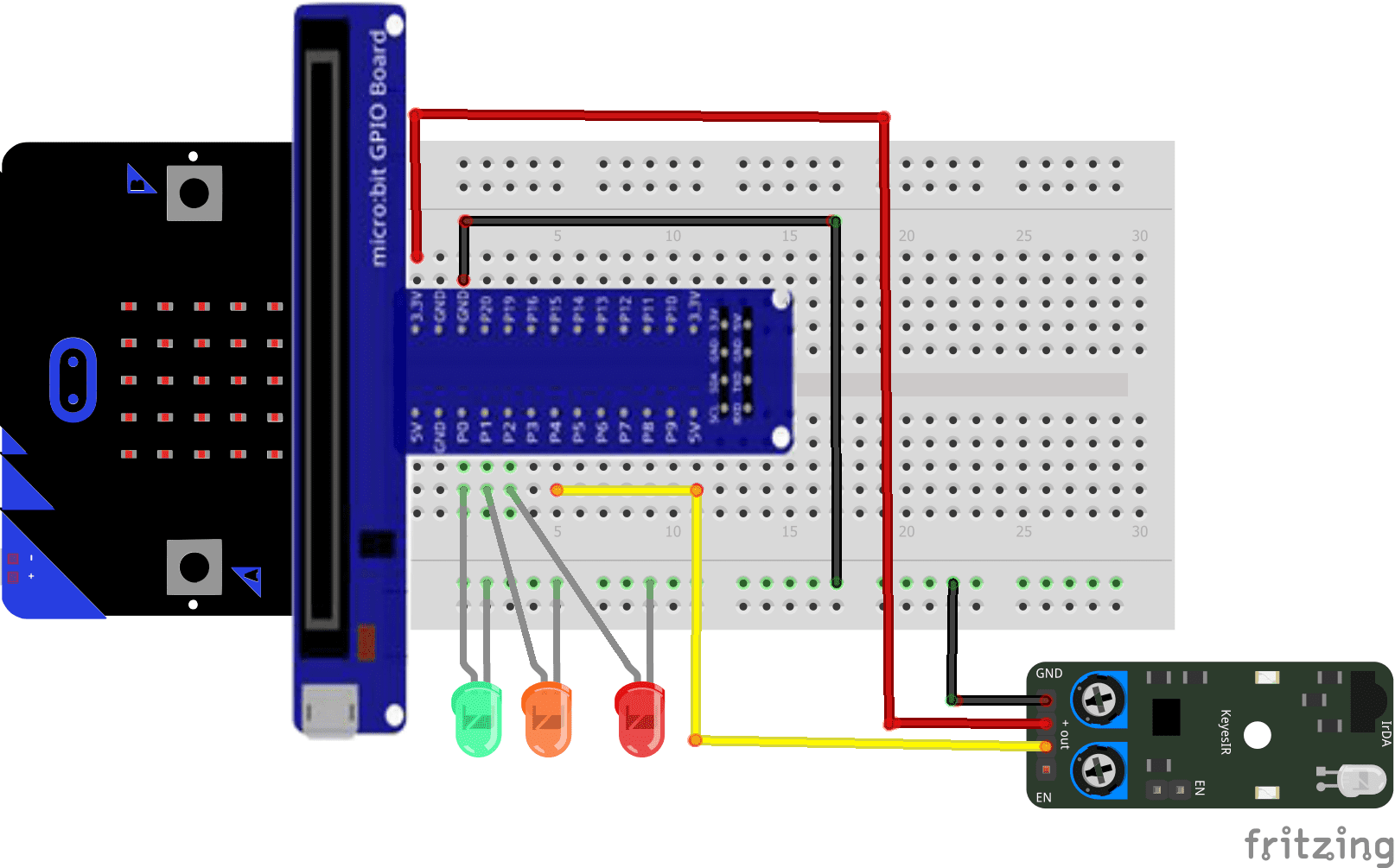
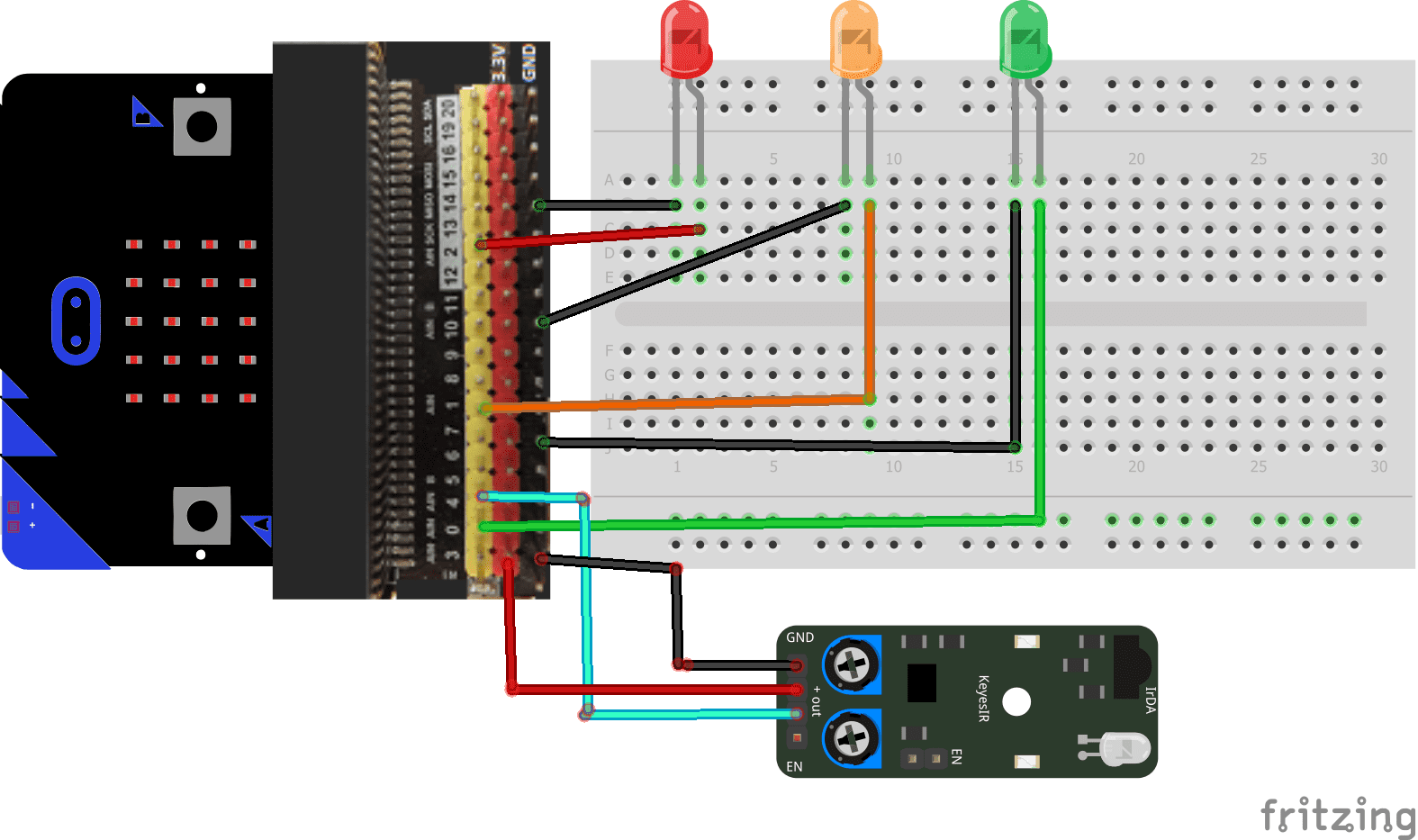
Mounting
To complete the assembly, you can connect the green LED to pin P0 , the yellow LED to pin P1 and the red LED to pin P2 of the micro:bit board.
For the IR sensor you can connect:
- Pin OUT to pin P4 of Micro:bit
- Pin (+) to pin 3.3V of Micro:bit
- Pin GND to GND of Micro:bit
The mounting methods are numerous and here are some examples:
Mounting (1)
Mounting (2)
Makecode program
You can also see

0 commentaire
Leave a comment


Recent tutorials


Most viewed tutorials


Most commented tutorials


Scroll to Top