KY-026 sensor Micro:bit Project
Fire detection system with Micro:bit
Presentation of fire detection system
A fire detection system is a set of devices and equipment that are designed to detect the presence of fire and to provide an alarm signal to alert building occupants and the fire department. There are several types of fire detection systems, including:
- Conventional fire detection systems: These systems use a network of sensors and alarm devices that are wired together. Each sensor is connected to a control panel, which monitors the sensors and sounds the alarm when a sensor detects a fire.
- Addressable fire detection systems: These systems use a network of sensors and alarm devices that communicate with a central control panel. Each sensor has a unique address, and the control panel can identify which sensor has detected the fire.
- Wireless fire detection systems: These systems use wireless sensors and alarms that communicate with a central control panel. Wireless systems are useful in situations where it is difficult or expensive to run wires.
- Smoke detection: Smoke detectors are devices that detect the presence of smoke and sound an alarm. Smoke detectors can be standalone devices or can be integrated into a larger fire detection system.
- Heat detection: Heat detectors are devices that detect the presence of heat and sound an alarm. Heat detectors can be standalone devices or can be integrated into a larger fire detection system.
- Flame detection: Flame detectors are devices that detect the presence of a flame and sound an alarm. Flame detectors can be standalone devices or can be integrated into a larger fire detection system.
- Carbon monoxide detection: Carbon monoxide detectors are devices that detect the presence of carbon monoxide and sound an alarm. Carbon monoxide detectors can be standalone devices or can be integrated into a larger fire detection system.
It is possible to use a Micro:bit to control a fire detection system, though it would likely need to be done as part of a larger system that includes sensors, alarms, and other components. The Micro:bit could be used to read input from fire sensors, such as smoke detectors or heat detectors, and then trigger an alarm or send a signal to the fire department in the event of a fire.
One possible way to accomplish this is to connect the Micro:bit to a network of fire sensors using its input and output pins. The Micro:bit could then read the signals from the sensors, and if a fire is detected, it could trigger an alarm or send a message to the fire department via a wired or wireless communication module.
Another possible way is to use the Micro:bit‘s built-in temperature sensor to detect heat, or a smoke sensor or flame sensor connected to it. The Micro:bit can then use its LEDs or buzzer to sound an alarm, or send a message via radio or Bluetooth to a central control panel or to the fire department.
Purpose of this project:
In this project a fire detection system with Micro:bit will be realized. It mainly uses a KY-026 flame sensor, buzzer and LED. When the flame sensor detects a fire, the Micro:bit board orders the buzzer to ring and the red LED to light up.
Required components
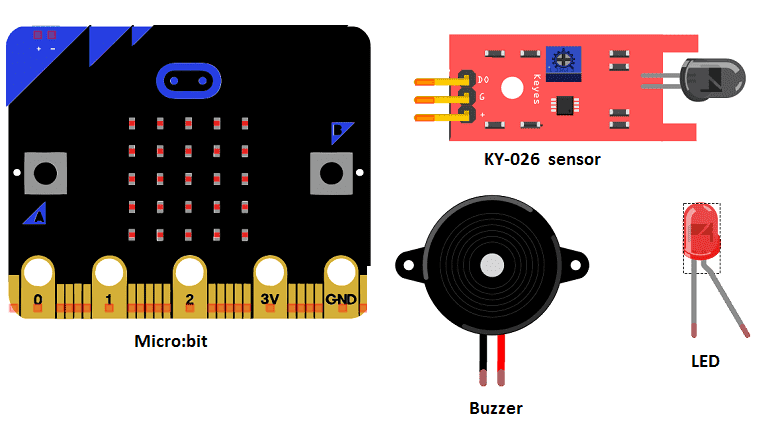
Micro:bit board
Micro:bit is a small, low-cost microcontroller board that was developed by the Micro:bit Educational Foundation for use in computer education. It is designed to be easy to use and accessible to a wide range of users, including children and beginners. The Micro:bit board measures about 4cm by 5cm and features a 25-pin edge connector, a 5×5 LED matrix, two programmable buttons, an accelerometer, a compass, a Bluetooth Low Energy (BLE) module, and a USB connector.
The Micro:bit is programmed using a variety of programming languages such as Python, JavaScript, and Microsoft Block Editor. It can be used to control a wide range of devices and projects, including robots, drones, lights, and more. The board can be powered by a USB cable or a 3V coin cell battery and can be programmed using a computer or mobile device.
The Micro:bit is widely used in education, providing a hands-on learning experience for students of all ages to learn computer programming, logic, and problem-solving. It’s also used by hobbyist and makers to create fun and interactive projects.
Microbit GPIO board
A Micro:bit GPIO (General Purpose Input/Output) Expansion Board is an accessory that can be used to extend the capabilities of a Micro:bit by providing additional input/output (I/O) pins. These pins can be used to connect sensors and actuators, such as LEDs, buttons, motors, and other electronic components.
The expansion board typically connects to the Micro:bit using a standard edge connector and provides a set of male headers that can be used to connect external components.
flame detector KY-026
The KY-026 is a module for the Micro:bit that includes a flame sensor. The module is used to detect the presence of a flame, and it outputs a digital signal that can be read by the Micro:bit. The output signal can be used to trigger an alarm or to send a signal to a central control system.
The KY-026 flame sensor module typically uses an infrared detector to detect the presence of a flame. The infrared detector is sensitive to the infrared radiation that is emitted by a flame. When a flame is detected, the module will output a high signal (usually 3.3V) to the Micro:bit. When the flame is not detected, the output signal is low (usually 0V).
The KY-026 module can be connected to the Micro:bit using its input/output pins and it can be programmed using the Micro:bit‘s software development kit (SDK).
buzzer
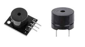
A buzzer is an electronic device that produces an audible sound when an electrical signal is applied to it. It can be used in a variety of applications, including alarms, doorbells, and other warning systems.
A buzzer can be connected to a Micro:bit using its input/output pins. The Micro:bit can then send a signal to the buzzer to turn it on and off, or to produce different sounds. The Micro:bit can also be programmed to control the frequency and duration of the sound produced by the buzzer, allowing for a wide range of different sounds and patterns.
The most common way to connect a buzzer to a Micro:bit is through a transistor or a relay, which acts as a switch to turn the buzzer on and off. This is done by sending a signal from the Micro:bit’s pin to the base of the transistor or relay, which then switches the power to the buzzer on or off.
1 red LED
![]()
A red LED (light-emitting diode) is a type of semiconductor device that emits light when an electric current is passed through it. It is commonly used as an indicator light in electronic devices, and it can also be used for lighting and other applications.
A red LED can be connected to a Micro:bit using its input/output pins. The Micro:bit can then send a signal to the LED to turn it on and off, or to change its brightness. The Micro:bit can also be programmed to control the flashing, blinking and fading of the LED, depending on the use case.
1 resistance 220Ω
![]()
Resistance is a measure of a material’s ability to oppose the flow of electric current. It is measured in ohms (Ω) and is represented by the Greek letter omega (Ω). The resistance of a material is determined by its composition and temperature.
In electrical circuits, resistance is an important factor that affects the amount of current flowing through the circuit. A circuit with high resistance will allow less current to flow through it than a circuit with low resistance. This can be useful in certain applications, such as controlling the brightness of an LED, or limiting the current flowing through a circuit to protect it from damage.
connecting wires

Connecting wires are used to connect various components in an electronic circuit. They allow for the transfer of electricity, data, or signals between different devices and components.
When connecting wires to an Arduino or other microcontroller, it is important to pay attention to the correct pinout. The pinout refers to the arrangement of pins on the microcontroller and the corresponding function of each pin. The Arduino pinout can be found in the documentation provided by the manufacturer, or in various resources available online.
test plate

A test plate, also known as a test jig, is a device used to test electronic circuits and components. It is a board or plate that has been designed to hold and connect various components and devices in a specific configuration, allowing for the easy testing and measurement of their performance.
A test plate can be used to test various types of electronic circuits and components, such as microcontrollers, sensors, and actuators. It typically includes connectors and sockets for connecting wires, power supply and measurement devices such as multimeters, oscilloscopes, and power supplies.
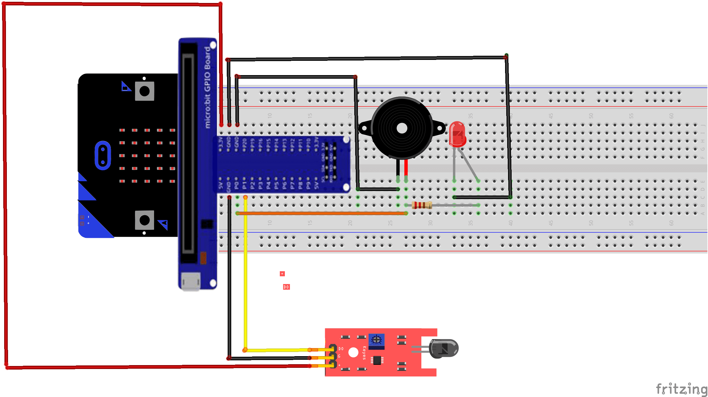
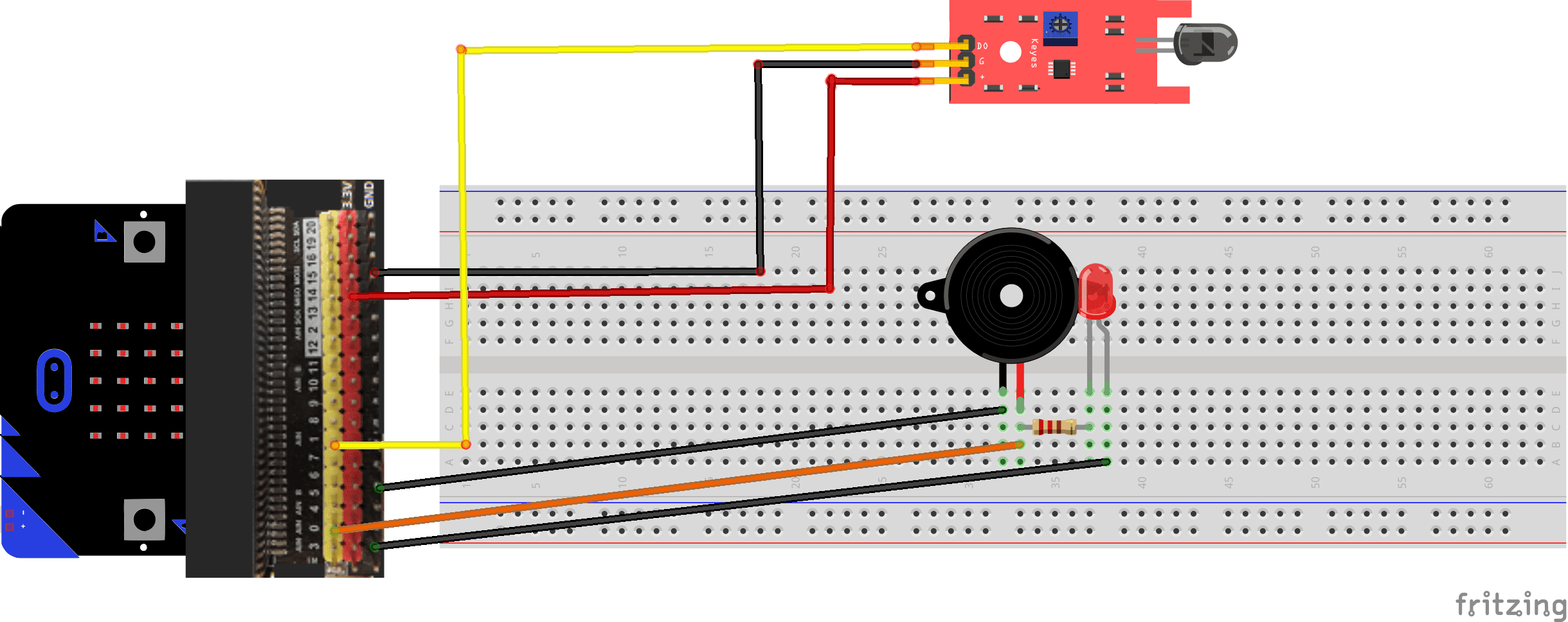
Mounting
To complete the assembly, you can connect
- the 2 terminals (+) of red LED and buzzer to the pin P0 of the Micro:bit
- the 2 terminals (-) of red LED and buzzer to the pin GND of the Micro:bit
- the pin DO of the flame sensor to the pin P1 of the Micro:bit board.
- the VCC pin of the flame sensor to the 3.3V pin of the Micro:bit board.
- the GND pin of the flame sensor to the GND pin of the Micro:bit board .
The mounting methods are numerous and here are some examples:
Mounting (1)
Mounting (2)
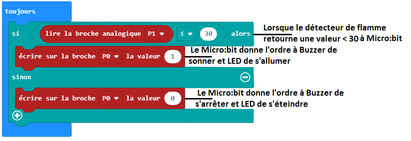
Makecode program
The Fire Detection System makecode program is as follows:
You can also see

0 commentaire
Leave a comment


Recent tutorials


Most viewed tutorials


Most commented tutorials


Scroll to Top