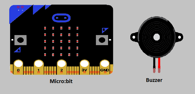
o use a buzzer with a Micro:bit, you will need to connect the buzzer to the Micro:bit‘s pins. The buzzer typically has two wires, one for the positive voltage (usually labeled as “+” or “VCC”) and one for the negative voltage (usually labeled as “-” or “GND”). The positive wire should be connected to one of the Micro:bit‘s digital output pins (such as pin 0 or pin 1) and the negative wire should be connected to one of the Micro:bit‘s GND pins.
Once the buzzer is connected, you can use the Micro:bit’s built-in music library to play notes and create melodies.
Purpose of this tutorial:
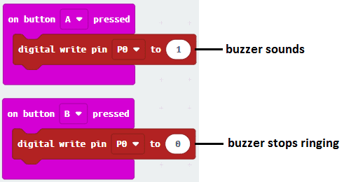
The goal of this tutorial is to find out how to use the buzzer with micro: bit: When you press button A, the buzzer emits a sound. When you press button B, the buzzer stops the sound emission.
Components required
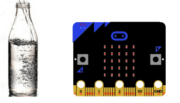
Micro:bit board
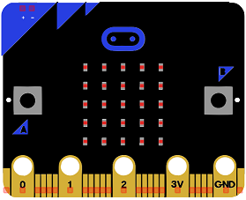
Micro:bit is a small, low-cost microcontroller board that was developed by the Micro:bit Educational Foundation for use in computer education. It is designed to be easy to use and accessible to a wide range of users, including children and beginners. The Micro:bit board measures about 4cm by 5cm and features a 25-pin edge connector, a 5×5 LED matrix, two programmable buttons, an accelerometer, a compass, a Bluetooth Low Energy (BLE) module, and a USB connector.
The Micro:bit is programmed using a variety of programming languages such as Python, JavaScript, and Microsoft Block Editor. It can be used to control a wide range of devices and projects, including robots, drones, lights, and more. The board can be powered by a USB cable or a 3V coin cell battery and can be programmed using a computer or mobile device.
The Micro:bit is widely used in education, providing a hands-on learning experience for students of all ages to learn computer programming, logic, and problem-solving. It’s also used by hobbyist and makers to create fun and interactive projects.
Microbit GPIO board
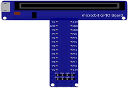
A Micro:bit GPIO (General Purpose Input/Output) Expansion Board is an accessory that can be used to extend the capabilities of a Micro:bit by providing additional input/output (I/O) pins. These pins can be used to connect sensors and actuators, such as LEDs, buttons, motors, and other electronic components.
The expansion board typically connects to the Micro:bit using a standard edge connector and provides a set of male headers that can be used to connect external components.
buzzer
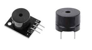
A buzzer is a type of electronic device that produces an audible sound or tone. It is typically a small, inexpensive component that can be easily integrated into a variety of electronic devices. There are several different types of buzzers, including piezoelectric buzzers and electromagnetic buzzers.
Piezoelectric buzzers use the piezoelectric effect to produce sound. They have a small ceramic element that vibrates when a voltage is applied to it, which creates the sound.
Electromagnetic buzzers use an electromagnet to vibrate a diaphragm, which creates the sound. They typically have a higher volume and a more stable frequency than piezoelectric buzzers.
Buzzers can be used in a variety of applications, such as alarms, timers, and indicators. They can be controlled with a microcontroller or other electronic device, which allows for a wide range of sound patterns and melodies to be created.
connecting wires

Connecting wires are used to connect various components in an electronic circuit. They allow for the transfer of electricity, data, or signals between different devices and components.
When connecting wires to an Arduino or other microcontroller, it is important to pay attention to the correct pinout. The pinout refers to the arrangement of pins on the microcontroller and the corresponding function of each pin. The Arduino pinout can be found in the documentation provided by the manufacturer, or in various resources available online.
test plate

A test plate, also known as a test jig, is a device used to test electronic circuits and components. It is a board or plate that has been designed to hold and connect various components and devices in a specific configuration, allowing for the easy testing and measurement of their performance.
A test plate can be used to test various types of electronic circuits and components, such as microcontrollers, sensors, and actuators. It typically includes connectors and sockets for connecting wires, power supply and measurement devices such as multimeters, oscilloscopes, and power supplies.
Mounting
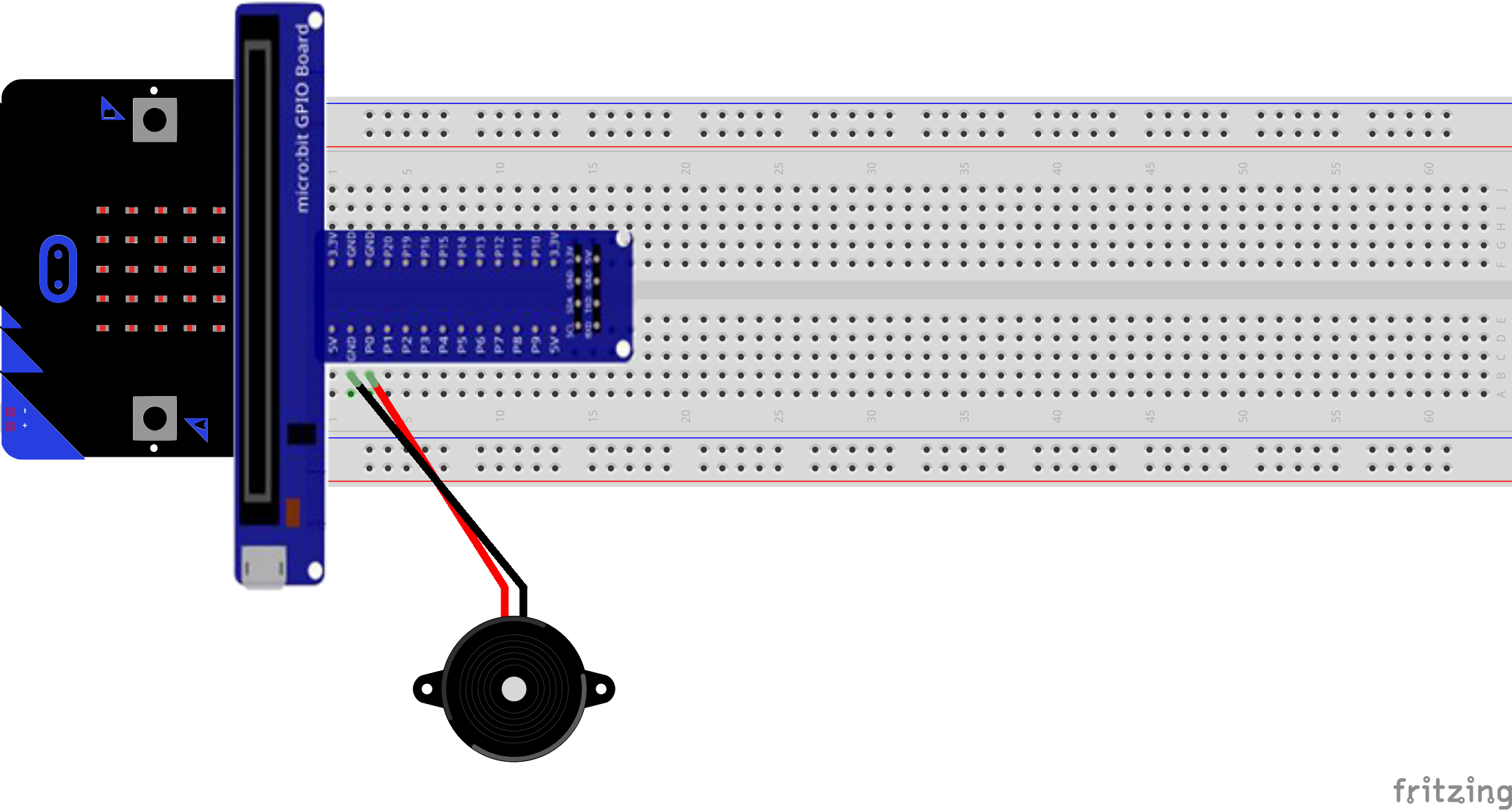
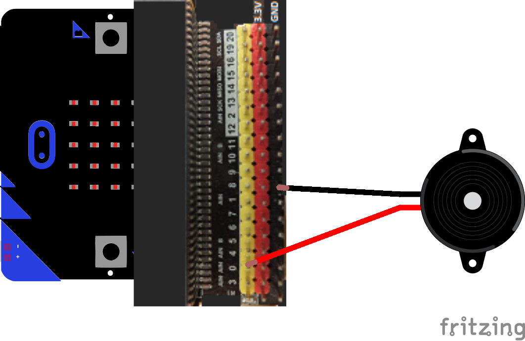
The assembly consists in connecting the terminal (+) of the buzzer to pin P0 and the terminal (-) to the GND of the micro: bit.
There are several mounting methods.
Mounting (1)
Mounting (2)
Makecode program
Here is the makecode program which makes it possible to emit a sound from the buzzer when the A button of the micro: bit is pressed.
You can also see

0 commentaire
Leave a comment


Recent tutorials


Most viewed tutorials


Most commented tutorials


Scroll to Top