Purpose of this tutorial:
Running a DC motor with Arduino in both directions can be achieved by using a motor driver or H-bridge to control the direction of the motor. A motor driver is an electronic device that can control the speed and direction of a DC motor. An H-bridge is a circuit that can be used to control the direction of a DC motor by reversing the polarity of the voltage applied to the motor.
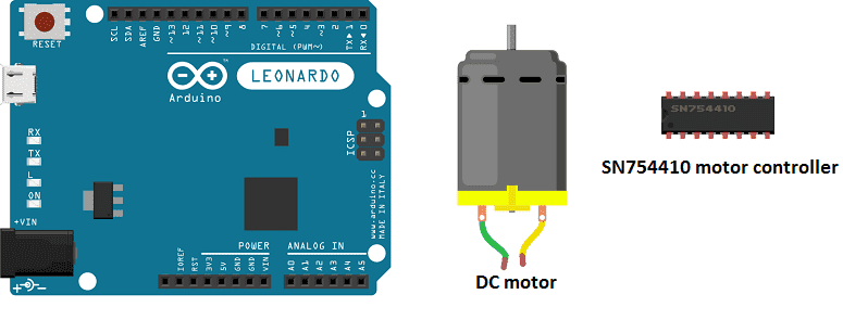
To run a DC motor in both directions using an Arduino and a motor driver, you would need the following components:
- An Arduino microcontroller such as an Arduino Uno or Mega
- SN754410 motor controller
- A DC motor
- Wires to connect everything together
The motor driver would be connected to the Arduino and the DC motor as per the manufacturer’s instructions. The motor driver would have control pins for controlling the direction and speed of the motor. The Arduino would then use digital output pins to send signals to the motor driver to control the direction and speed of the motor.
To change the direction of the motor, the Arduino would send a signal to the motor driver to change the polarity of the voltage applied to the motor terminals. The motor driver would then apply the voltage to the correct terminals, reversing the direction of the motor.
Alternatively, you can use an H-bridge circuit, which is a type of circuit that can be used to control the direction of a DC motor by reversing the polarity of the voltage applied to the motor. An H-bridge can be built using transistors, MOSFETs, or other electronic components.
It’s worth noting that, running a DC motor in both directions with an Arduino requires knowledge of electronics and programming and proper planning and design to ensure the circuit is safe to operate and the motor is not damaged. Additionally, the system would require regular maintenance and updates to ensure it continues to function correctly.
In this tutorial we will order a DC motor by the Arduino board in both directions:
- the DC motor rotates in a direct direction for 3 seconds.
- Then it rotates in an indirect direction for 3 seconds.
- Finally It stops for 1 second and we start step 1.
Necessary components
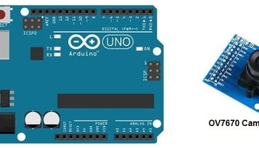
Arduino UNO
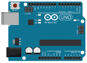
The Arduino UNO is a microcontroller board based on the ATmega328P. It has 14 digital input/output pins, 6 analog inputs, a 16 MHz quartz crystal, a USB connection, a power jack, an ICSP header, and a reset button. It is the most popular and widely used board among the Arduino boards.
The Arduino UNO can be programmed using the Arduino programming language, which is based on C++. It uses a simple and intuitive programming environment, making it easy for beginners to get started with microcontroller programming.
The Arduino UNO can be connected to various sensors and actuators to control different devices and perform different tasks. For example, it can be used to control motors, read data from sensors, display information on an LCD screen, and communicate with other devices via serial communication protocols such as I2C and SPI.
The Arduino UNO can also be powered by a USB cable or an external power supply, making it easy to use in a wide range of projects and applications. It’s compatible with a wide range of shields (expansion boards) that adds functionality to the board, such as Ethernet, WiFi, and Bluetooth, and it’s widely supported by a strong and active community, which provides a lot of tutorials, examples and libraries to help users to get the most of the board.
5V DC Motor
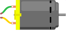
A 5V DC motor is a type of electric motor that runs on 5 volts DC (direct current) power. It is a type of small and low-cost motor that is commonly used in small-scale and hobby projects, such as robot cars, drones, and other types of mobile devices.
A 5V DC motor typically includes a rotor (the rotating part of the motor) and a stator (the stationary part of the motor). The rotor is typically a permanent magnet, and the stator is typically a set of coils of wire. When a current is applied to the coils of wire, it creates a magnetic field that interacts with the magnetic field of the rotor, causing the rotor to rotate.
5V DC motors can be controlled by a microcontroller such as an Arduino or a Raspberry Pi, by connecting the motor to an output pin of the microcontroller and writing a program to control the state of the pin. A motor driver can also be used to control the speed and direction of the motor.
SN754410 motor controller
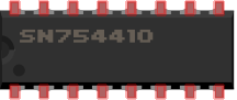
The SN754410 is a type of H-bridge motor controller IC (integrated circuit) that can be used to control the direction and speed of a DC motor. An H-bridge is a circuit that can be used to control the direction of a DC motor by reversing the polarity of the voltage applied to the motor.
The SN754410 is a quadruple half-H driver, which means it can control four motors and it uses four inputs to control the direction and speed of the motors. The IC has two input pins for controlling the direction of each motor and two input pins for controlling the speed of each motor. The IC also includes protection diodes to protect the IC from voltage spikes generated by the motor.
To use the SN754410 to control a DC motor, you would need to connect the motor to the IC’s motor terminals, connect the IC’s control pins to an appropriate microcontroller such as an Arduino and provide power to the IC. The microcontroller would then send signals to the IC to control the direction and speed of the motor.
4 batteries of 1.5V
connecting wires

Connecting wires are used to connect various components in an electronic circuit. They allow for the transfer of electricity, data, or signals between different devices and components.
When connecting wires to an Arduino or other microcontroller, it is important to pay attention to the correct pinout. The pinout refers to the arrangement of pins on the microcontroller and the corresponding function of each pin. The Arduino pinout can be found in the documentation provided by the manufacturer, or in various resources available online.
test plate

A test plate, also known as a test jig, is a device used to test electronic circuits and components. It is a board or plate that has been designed to hold and connect various components and devices in a specific configuration, allowing for the easy testing and measurement of their performance.
A test plate can be used to test various types of electronic circuits and components, such as microcontrollers, sensors, and actuators. It typically includes connectors and sockets for connecting wires, power supply and measurement devices such as multimeters, oscilloscopes, and power supplies.
Mounting
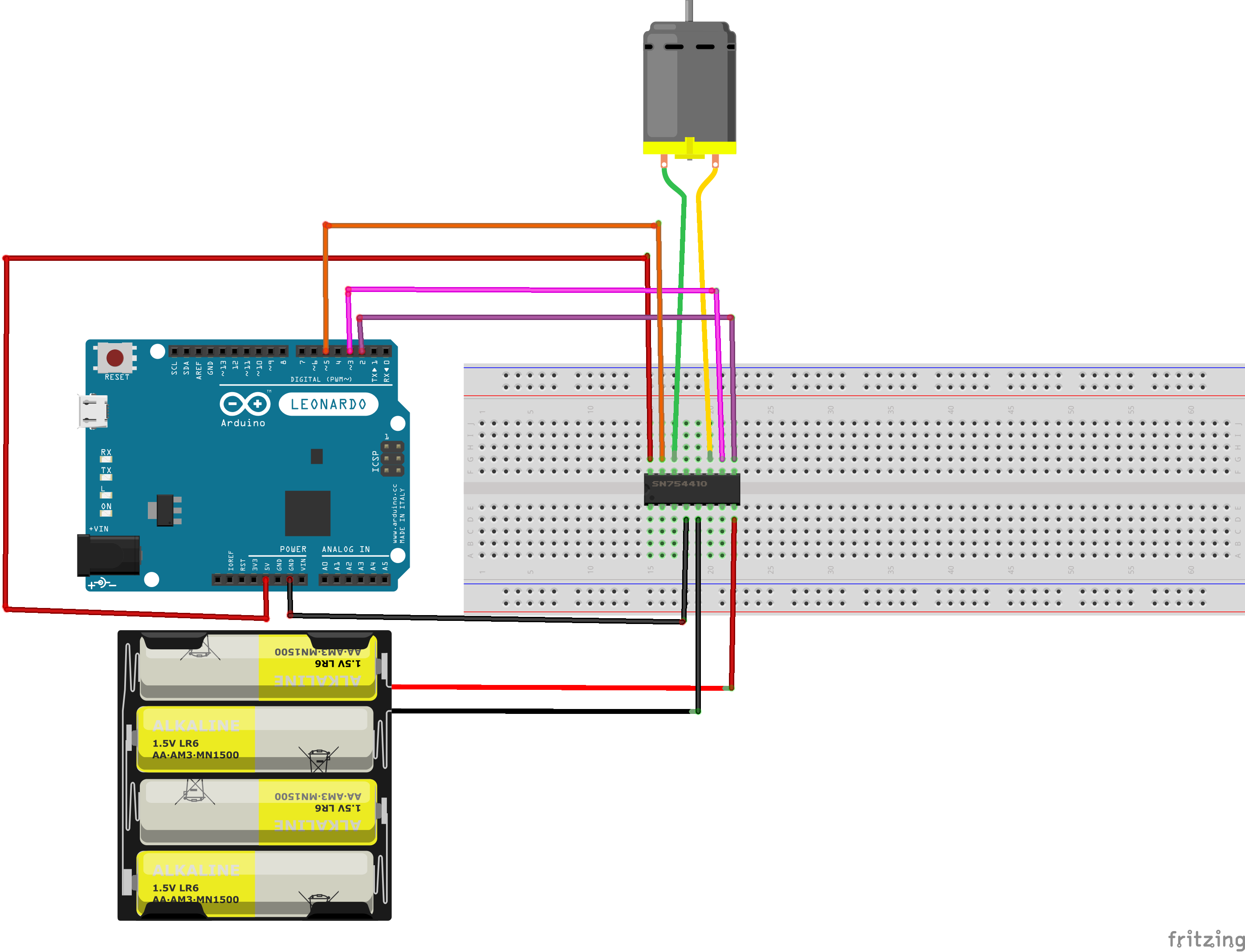
Program
Here is the program that allows to control a DC motor by the Arduino.
|
1 2 3 4 5 6 7 8 9 10 11 12 13 14 15 16 17 18 19 20 21 22 23 24 25 26 27 28 29 30 31 32 33 |
// Constants const int enableBridge1 = 2; const int MotorForward1 = 3; const int MotorReverse1 = 5; // Variables int Power = 80; //Motor velocity between 0 and 255 void setup(){ pinMode(MotorForward1,OUTPUT); pinMode(MotorReverse1,OUTPUT); pinMode(enableBridge1,OUTPUT); } void loop(){ digitalWrite(enableBridge1,HIGH); // Active pont en H // Rotates in a direct direction for 3 seconds analogWrite(MotorForward1,Power); analogWrite(MotorReverse1,0); delay(3000); // Rotates in reverse direction for 3 seconds analogWrite(MotorForward1,0); analogWrite(MotorReverse1,Power); delay(3000); //Stops the DC motor for 1 second analogWrite(MotorForward1,0); analogWrite(MotorReverse1,0); digitalWrite(enableBridge1,LOW); delay(1000); } |
You can also see

0 commentaire
Leave a comment


Recent tutorials


Most viewed tutorials


Most commented tutorials


Scroll to Top