Presentation of robot car
A robot car is a type of robot that is designed to move on wheels or tracks, like a vehicle. It is typically controlled by a microcontroller, such as an Arduino or a Raspberry Pi, and can be programmed to move, sense its environment, and perform various tasks.
A robot car can be built using a variety of different components and technologies, depending on the specific application and design. The basic components of a robot car include a chassis, wheels or tracks, a microcontroller, and some type of power source such as batteries. Additional components may include sensors, such as ultrasonic sensors, infrared sensors, or cameras, to sense the environment, and actuators, such as motors, to control the movement of the robot.
There are different types of robot cars, some are controlled by a remote control, others have the ability to navigate autonomously using sensors and algorithms. Autonomous robot cars can be programmed to follow a pre-defined path, avoid obstacles, or even perform tasks such as mapping and exploration.
Building a robot car can be a fun and educational project, and it can be a good way to learn about robotics, electronics, and programming. However, it is important to note that building a robot car can be a challenging and time-consuming process that requires knowledge and experience in electronics, programming, and mechanics. Additionally, it’s important to ensure that the robot car is safe to operate, and it should be tested thoroughly before using it.
Presentation of a remote control car with Arduino
A remote control car with Arduino is a type of robot car that is controlled by an Arduino microcontroller and a remote control device. The Arduino receives signals from the remote control and uses them to control the movement of the car.
To build a remote control car with Arduino, you would need the following components:
- An Arduino microcontroller such as an Arduino Uno or Mega
- Motors and wheels to provide movement to the car
- A motor driver to control the motors
- A remote control receiver to receive signals from the remote control
- Batteries to power the car
- A chassis to hold all the components
- Wires to connect everything together
The Arduino would be programmed to receive the signals from the remote control receiver, and based on the received signals, it would control the movement of the motors by sending signals to the motor driver. The remote control can be any device that can send signals such as infrared or radio frequency.
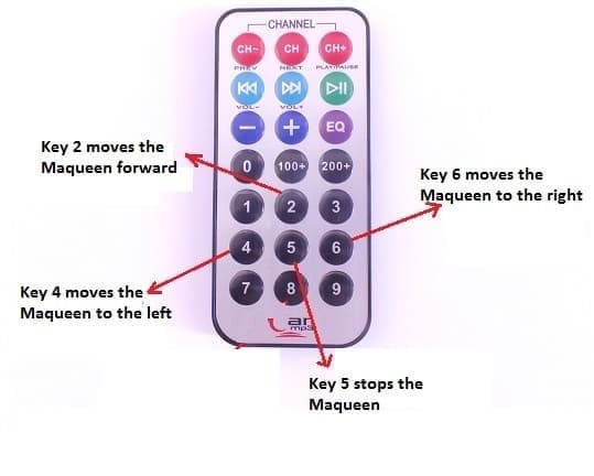
To control the car, the remote control will have buttons to move the car forward, backward, left and right. The Arduino program will be responsible for interpreting the signals sent by the remote control and translate them into actions on the car’s motors.
It’s worth noting that, building a remote control car with Arduino requires knowledge of electronics, programming and mechanics, as well as proper planning and design to ensure the car is safe to operate. Additionally, the system would require regular maintenance and updates to ensure it continues to function correctly.
Purpose of this project:
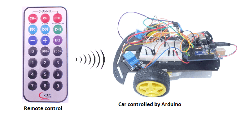
In this project we will build a remotely controlled car (by infrared) controllable by the Arduino board.
The user will be able to drive the car by a remote control in three directions (forward, right and left) and stop it.
necessary components
Arduino UNO
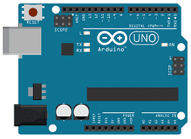
The Arduino UNO is a microcontroller board based on the ATmega328P. It has 14 digital input/output pins, 6 analog inputs, a 16 MHz quartz crystal, a USB connection, a power jack, an ICSP header, and a reset button. It is the most popular and widely used board among the Arduino boards.
The Arduino UNO can be programmed using the Arduino programming language, which is based on C++. It uses a simple and intuitive programming environment, making it easy for beginners to get started with microcontroller programming.
The Arduino UNO can be connected to various sensors and actuators to control different devices and perform different tasks. For example, it can be used to control motors, read data from sensors, display information on an LCD screen, and communicate with other devices via serial communication protocols such as I2C and SPI.
The Arduino UNO can also be powered by a USB cable or an external power supply, making it easy to use in a wide range of projects and applications. It’s compatible with a wide range of shields (expansion boards) that adds functionality to the board, such as Ethernet, WiFi, and Bluetooth, and it’s widely supported by a strong and active community, which provides a lot of tutorials, examples and libraries to help users to get the most of the board.
Two relays
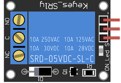
A relay is an electrically operated switch that can be used to control the flow of electricity to a motor or other device. A relay is typically used in situations where a low-voltage control circuit needs to switch a higher-voltage power circuit.
When a relay is used to control a motor, the relay is connected to the motor’s power supply and the control circuit is connected to the relay’s input. When the control circuit sends a signal to the relay, the relay‘s internal switch is activated, allowing power to flow to the motor. This allows the control circuit, which is typically a low-voltage circuit, to control a high-voltage circuit, such as a motor.
The relay can be controlled by an Arduino or other microcontroller, by sending a signal to the relay‘s input. This can be done by connecting the relay to an output pin of the Arduino and writing a program to control the state of the pin.
Remote control
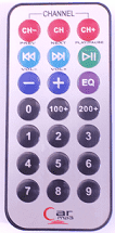
A remote control is a device that allows for the remote operation of an electronic device or system. Remote controls can be used to control a wide range of devices such as televisions, air conditioners, cars, robots, and more. Remote controls typically use wireless technology such as infrared (IR) or radio frequency (RF) to send control signals to the device or system.
A remote control typically includes a set of buttons or a keypad that can be used to send control signals to the device or system. These buttons or keypad are usually labeled with the functions they control, such as power, volume, channel, or movement. Remote controls can also include additional features such as a display, a microphone, or an accelerometer.
A remote control is used to control the movement and actions of a robot car
IR sensor
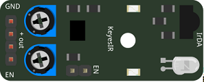
The KY-032 is an infrared obstacle sensor module that is used to detect obstacles in front of a robot or other device. While it is primarily used for obstacle detection, it cannot be used for remote control directly. Remote control refers to the ability to control the movement and actions of a device or system wirelessly using a remote control or a smartphone.
In order to remotely control a robot car that uses the KY-032 obstacle sensor module, you would need to use a wireless communication module such as a radio frequency (RF) module or a Bluetooth module to establish a wireless connection between the robot car and the remote control device. The wireless control device, such as a remote control or a smartphone, would send control signals to the robot car via this wireless connection.
The robot car’s microcontroller, such as an Arduino, would be programmed to receive and interpret these control signals and then control the movement of the car’s motors and other actions based on the received control signals. The KY-032 obstacle sensor module would be used to detect obstacles in front of the robot car and send a signal to the microcontroller to take appropriate actions, such as stopping or avoiding the obstacle.
It’s worth noting that, while the KY-032 obstacle sensor module is not used directly for remote control, it can be used in conjunction with other components to create a remote controlled robot car. Additionally, it’s important to ensure the robot car is safe and reliable and the wireless communication is secure to prevent unauthorized access.
2 wheel car robot kit
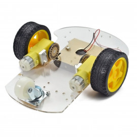
A 2-wheel car robot kit is a collection of components that can be used to build a small, autonomous robot that moves on two wheels. These kits typically include a microcontroller, such as a ESP32 card, to control the robot’s movements, as well as motors, wheels, and other hardware to enable the robot to move and navigate.
2-wheel car robots are often used as educational tools, as they can be used to teach basic principles of robotics, electronics, and programming. They can also be used as a platform for experimenting with different control algorithms, sensors, and other hardware.
This robot kit is composed of:
-
car chassis.
-
2 gear motors (1:48)
-
2 car tires
-
1 universal wheel
connecting wires

Connecting wires are used to connect various components in an electronic circuit. They allow for the transfer of electricity, data, or signals between different devices and components.
When connecting wires to an Arduino or other microcontroller, it is important to pay attention to the correct pinout. The pinout refers to the arrangement of pins on the microcontroller and the corresponding function of each pin. The Arduino pinout can be found in the documentation provided by the manufacturer, or in various resources available online.
test plate

A test plate, also known as a test jig, is a device used to test electronic circuits and components. It is a board or plate that has been designed to hold and connect various components and devices in a specific configuration, allowing for the easy testing and measurement of their performance.
A test plate can be used to test various types of electronic circuits and components, such as microcontrollers, sensors, and actuators. It typically includes connectors and sockets for connecting wires, power supply and measurement devices such as multimeters, oscilloscopes, and power supplies.
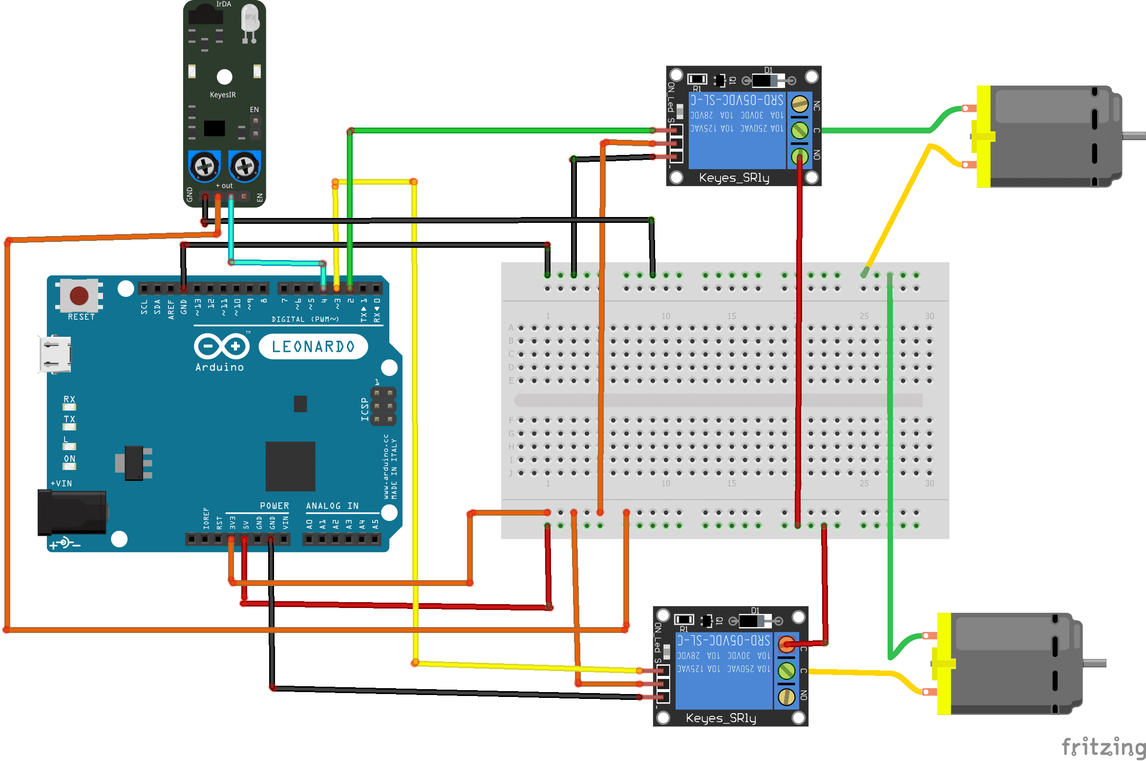
Construction of the car
Assembly of the car with Arduino
Pour réaliser le montage, on peut connec ter:
For first relay:
- (S) pin to pin 2 of Arduino
- (+) pin to 3.3V pin of Arduino
- (-) pin to GND pin of Arduino
- ON pin to 5V pin of Arduino
For second relay:
- S) pin to pin 3 of Arduino
- (+) pin to 3.3V pin of Arduino
- (-) pin to GND pin of Arduino
- ON pin to 5V pin of Arduino
For each of the two motors:
- first terminal to COM pin of relay
- second terminal to GND pin of Arduino
For IR sensor:
- OUT pin to pin 4 of Arduino
- (+) pin to 3.3V pin of Arduino
- GND pin to GND pin of Arduino
Program
Here is the program for the Arduino connected to the car:
#include <IRremote.h>
int RECV_PIN = 4;
IRrecv irrecv(RECV_PIN); // IR sensor connected to pin 4 of Arduino
decode_results results;
const int relais_moteur1 = 2; // relay connected to pin 2 of Adruino
const int relais_moteur2 = 3; // // relay connected to pin 3 of Adruino
void setup()
{ irrecv.enableIRIn(); ////Initializes the infrared receiver
pinMode(relais_moteur1, OUTPUT);
pinMode(relais_moteur2, OUTPUT);
}
void loop()
{ if (irrecv.decode(&results)) {
if (results.value==0xFF18E7)//press the 2 key
{
digitalWrite(relais_moteur1, HIGH);// the car is moving forward
digitalWrite(relais_moteur2, HIGH);
}
if (results.value==0xFF5AA5)//press the 6 key
{
digitalWrite(relais_moteur1, HIGH);
digitalWrite(relais_moteur2, LOW); // the car is moving right
}
if (results.value==0xFF10EF)//press the 4 key
{
digitalWrite(relais_moteur1, LOW);
digitalWrite(relais_moteur2, HIGH); //the car is moving left
}
if (results.value==0xFF38C7)// press the 5 key
{
digitalWrite(relais_moteur1, LOW);// car stops
digitalWrite(relais_moteur2, LOW);
}
irrecv.resume(); // Get the following value
}
}
You can also see

0 commentaire
Leave a comment


Recent tutorials


Most viewed tutorials


Most commented tutorials


Scroll to Top