Purpose of this tutorial:
In this tutorial we will control the ignition of an RGB LED via the two buttons A and B of the micro:bit card:
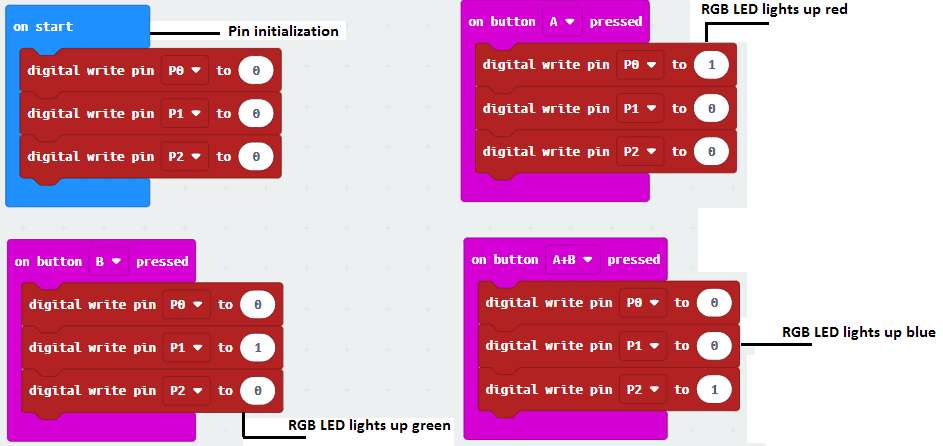
1- When we press the button A, the LED lights up in red.
2- When you press the B button, the LED lights up green.
3- When you press the 2 buttons A and B at the same time, the LED lights up blue.
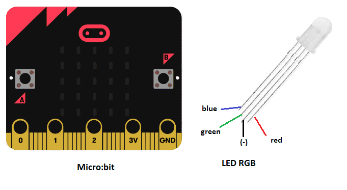
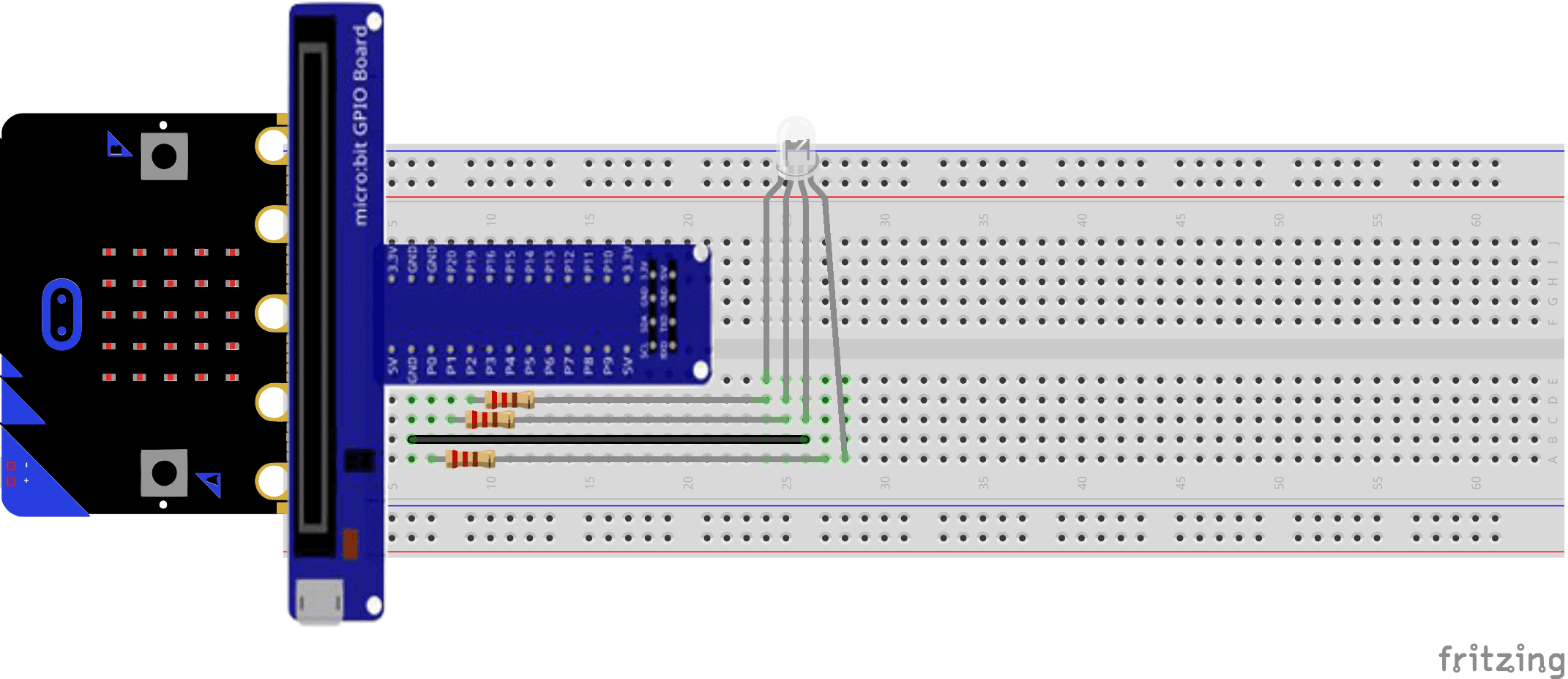
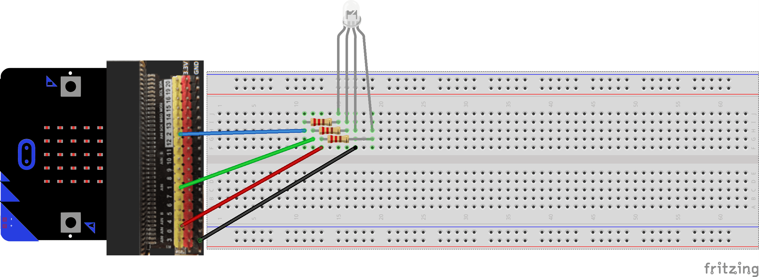
Assembly Connect:
- Pin Po from the Micro:bit board to pin (R) for the red color of the RGB LED module
- Pin P1 from the Micro:bit board to pin (G) for the green color of the RGB LED module
- Pin P2 from the Micro:bit board to pin (B) for the blue color of the RGB LED module
- the GND pin of the micro:bit to pin (GND) board of the RGB LED module
Required components
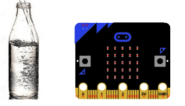
Micro:bit board
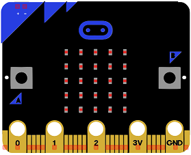
Micro:bit is a small, low-cost microcontroller board that was developed by the Micro:bit Educational Foundation for use in computer education. It is designed to be easy to use and accessible to a wide range of users, including children and beginners. The Micro:bit board measures about 4cm by 5cm and features a 25-pin edge connector, a 5×5 LED matrix, two programmable buttons, an accelerometer, a compass, a Bluetooth Low Energy (BLE) module, and a USB connector.
The Micro:bit is programmed using a variety of programming languages such as Python, JavaScript, and Microsoft Block Editor. It can be used to control a wide range of devices and projects, including robots, drones, lights, and more. The board can be powered by a USB cable or a 3V coin cell battery and can be programmed using a computer or mobile device.
The Micro:bit is widely used in education, providing a hands-on learning experience for students of all ages to learn computer programming, logic, and problem-solving. It’s also used by hobbyist and makers to create fun and interactive projects.
Microbit GPIO board
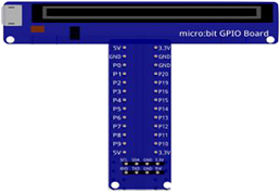
A Micro:bit GPIO (General Purpose Input/Output) Expansion Board is an accessory that can be used to extend the capabilities of a Micro:bit by providing additional input/output (I/O) pins. These pins can be used to connect sensors and actuators, such as LEDs, buttons, motors, and other electronic components.
The expansion board typically connects to the Micro:bit using a standard edge connector and provides a set of male headers that can be used to connect external components.
LED RGB
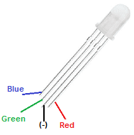
LED RGB stands for Light Emitting Diode Red Green Blue. It refers to a type of LED that can emit light in different colors by adjusting the intensity of the red, green, and blue light emitting diodes. This allows for a wide range of color options and the ability to create dynamic color-changing effects. They are commonly used in lighting fixtures, displays, and other electronic devices.
3 Resistors of 22O Ω
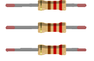
Resistance is a measure of a material’s opposition to the flow of electric current. It is measured in ohms (Ω) and is represented by the symbol “R”. The more resistance a material has, the less current will flow through it when a given voltage is applied. Conversely, the less resistance a material has, the more current will flow through it when a given voltage is applied.
connecting wires

Connecting wires are used to connect various components in an electronic circuit. They allow for the transfer of electricity, data, or signals between different devices and components.
When connecting wires to an Arduino or other microcontroller, it is important to pay attention to the correct pinout. The pinout refers to the arrangement of pins on the microcontroller and the corresponding function of each pin. The Arduino pinout can be found in the documentation provided by the manufacturer, or in various resources available online.
test plate

A test plate, also known as a test jig, is a device used to test electronic circuits and components. It is a board or plate that has been designed to hold and connect various components and devices in a specific configuration, allowing for the easy testing and measurement of their performance.
A test plate can be used to test various types of electronic circuits and components, such as microcontrollers, sensors, and actuators. It typically includes connectors and sockets for connecting wires, power supply and measurement devices such as multimeters, oscilloscopes, and power supplies.
The mounting
methods are numerous and here are some examples:
Mounting (1)
Mounting (2)
Program makecode
Here is the program makecode which allows to control the ignition of an RGB LED with the buttons of the micro:bit.
You can also see

0 commentaire
Leave a comment


Recent tutorials


Most viewed tutorials


Most commented tutorials


Scroll to Top