App Inventor Arduino
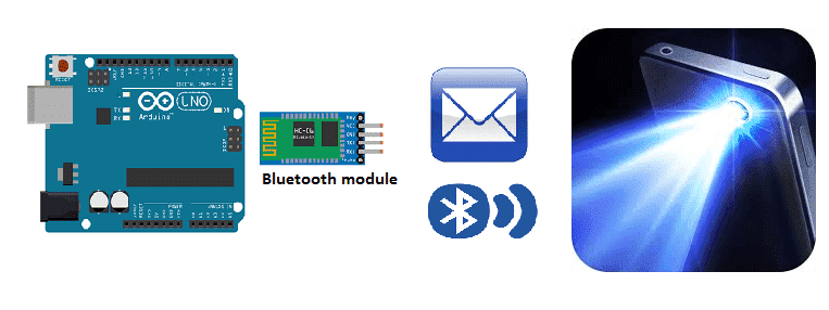
Turn on the smartphone torch by Arduino
Sending data from an Arduino to a smartphone via Bluetooth
To send data from an Arduino to a smartphone via Bluetooth, you will need a Bluetooth module, such as the HC-06, and a smartphone with Bluetooth capabilities. Here is a general overview of the process:
- Connect the HC-06 Bluetooth module to the Arduino. The module should be connected to the Arduino‘s serial pins (RX, TX) and powered by the Arduino‘s voltage supply.
- Upload a sketch to the Arduino that sends data via the serial connection. You can use the Serial.begin() and Serial.print() functions in Arduino to send data from the Arduino to the HC-06 module.
- Pair the HC-06 module with your smartphone. On your smartphone, go to the Bluetooth settings and search for available devices. Once the HC-06 is found, pair with it using the default password “1234” or “0000”
- Use a software or an application on your smartphone that can receive the data sent by the Arduino. One of the most common one is the “Serial Bluetooth Terminal” this app allows you to see the data sent by the Arduino.
- Configure the software or app to receive data from the HC-06 module.
- Once everything is set up, the Arduino should be able to send data to the smartphone via the HC-06 Bluetooth module. The data can be displayed on the smartphone‘s screen or used to control other functions on the smartphone.
Purpose of this tutorial:
To turn on the smartphone torch by using an Arduino via Bluetooth, you will need the following components:
- HC-06 Bluetooth module
- Arduino board
- Jumper wires
- Smartphone with Bluetooth capabilities and a torch feature
- A software or an application on your smartphone that can receive commands sent by the Arduino.
Here is a general overview of the process:
- Connect the HC-06 Bluetooth module to the Arduino. The module should be connected to the Arduino’s serial pins (RX, TX) and powered by the Arduino’s voltage supply.
- Upload a sketch to the Arduino that sends commands via the serial connection. In this case, the command will be to turn on the torch of the smartphone. You can use the Serial.begin() and Serial.print() functions in Arduino to send the command to the HC-06 module.
- Pair the HC-06 module with your smartphone. On your smartphone, go to the Bluetooth settings and search for available devices. Once the HC-06 is found, pair with it using the default password “1234” or “0000”
- Use a software or an application on your smartphone that can receive commands sent by the Arduino. One of the most common one is the “Serial Bluetooth Terminal” this app allows you to see the commands sent by the Arduino.
- Configure the software or app to receive commands from the HC-06 module.
- Write a code on the arduino sketch that will turn the torch on when a specific command is received.
- Once everything is set up, the Arduino should be able to send the command to turn on the torch of the smartphone via the HC-06 Bluetooth module.
In this tutorial we will see how to turn on the smartphone torch using the Arduino board.
This is why we are going to create two programs: a mobile application with App Inventor for the smartphone and a program for the Arduino board.
Necessary components
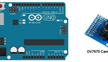
Arduino UNO
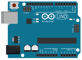
The Arduino UNO is a microcontroller board based on the ATmega328P. It has 14 digital input/output pins, 6 analog inputs, a 16 MHz quartz crystal, a USB connection, a power jack, an ICSP header, and a reset button. It is commonly used for DIY electronics projects and for controlling a variety of devices. The board can be programmed with the Arduino IDE (Integrated Development Environment) software, which is a simple programming language based on C/C++.
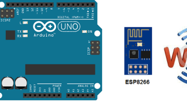
HC-06 Bluetooth module
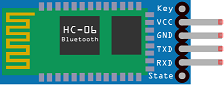
The HC-06 Bluetooth module is a small, inexpensive device that allows for wireless communication between electronic devices using the Bluetooth protocol. It can be used to connect microcontrollers such as an Arduino to a smartphone or computer, allowing for wireless control or data transfer.
The HC-06 module operates as a slave device and can be configured to work with a wide range of baud rates. It can be powered by a voltage between 3.3V and 6V and consumes very low power. It supports both AT and transparent transmission mode.
It can be easily interfaced with microcontroller using UART communication. The HC-06 module can be used to implement wireless control and monitoring of various electronic projects, and it can be easily integrated into existing projects to add wireless functionality.
Pushbutton
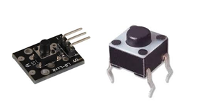
A pushbutton, also known as a switch, is a simple electrical component that allows a user to control an electrical circuit by physically pressing the button. When the button is pressed, it completes an electrical circuit, allowing electrical current to flow through the circuit, and when the button is released, the circuit is broken, stopping the flow of current.
Using a pushbutton with an Arduino is a simple and common task that can be accomplished using digital input pins. A pushbutton can be used to control various aspects of an Arduino project, such as starting and stopping a motor, turning on and off an LED, or sending a signal to a microcontroller to trigger an action.
Test plate

A test plate is a type of device used in robotics to test the functionality and performance of various components or systems. It is typically a physical platform or structure that is designed to hold and support various test items or devices, such as sensors, actuators, motors, or other types of mechanical or electrical components. Test plates can be used to simulate different environments or conditions, such as temperature, humidity, vibration, or other factors, in order to evaluate the performance of the components or systems being tested. They can also be used to perform a variety of diagnostic or diagnostic tests, such as stress testing, endurance testing, or other types of evaluations.
Connecting wires

Wires are used to transmit electrical signals and power to various components such as motors, sensors, and microcontrollers. It’s important to properly route and secure the wires to prevent tangles and damage. There are several methods for doing this, including using cable ties, clamps, and wire looms. It’s also a good idea to use different colors or labeling to identify the different wires and their functions. When connecting wires in a robot, it’s important to follow proper safety procedures, such as using the correct wire stripper and connectors, and wearing protective equipment such as gloves and safety glasses.
For the assembly you can see the following article:
https://www.robotique.tech/robotics/send-a-message-from-arduino-to-smartphone/
Program
Here is the program that allows you to connect the Arduino board to the smartphone and send a message containing the order to turn on the smartphone torch.
|
1 2 3 4 5 6 7 8 9 10 11 12 13 14 15 16 17 18 19 20 21 22 23 |
#include <SoftwareSerial.h> const int btnPin = A0; //the push button is connected to pin A0 of the Adruino int btnVal = 0; SoftwareSerial hc06(2,3); int allumer=0; void setup(){ pinMode(btnPin,INPUT_PULLUP); hc06.begin(9600); } void loop(){ btnVal=analogRead(btnPin); if(btnVal<200) // We press the push button {if (allumer==0){ hc06.print("allumer"); //send message to smartphone allumer=1; } else{ hc06.print("eteindre"); //send message to smartphone allumer=0; }delay(500); } } |
Creation of the application with App Inventor:
We are going to create a mobile application named ‘allumer_torche_arduino’ with App Inventor which allows you to receive a message from the Arduino board.
We propose to create the design of the application, with the following visual:
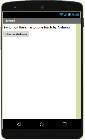
Programming with App Inventor
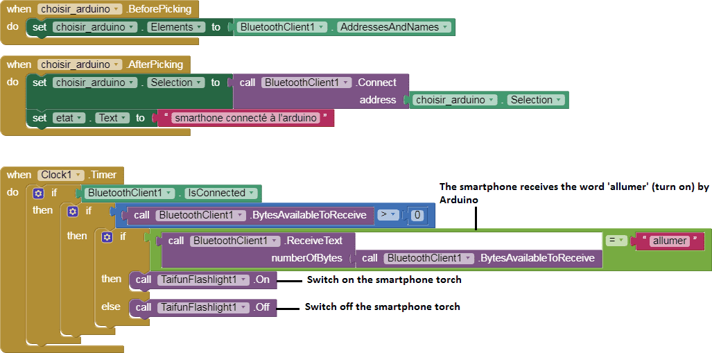
To program the application, App Inventor offers us to use the Blocks space, which allows you to create a program in the form of a block diagram. Very easy to use but requiring a little programming logic.
Here is the program of the application created in the Blocks area of the Inventor App:
You can also see

1 commentaire
Leave a comment


Recent tutorials


Most viewed tutorials


Most commented tutorials


Scroll to Top
sitemap.xml 11-11-2323
Thee oother day, while I was aat work, mmy sister stolpe my iPaad and tested tto seee iif it can survive a 40 foot drop, just so shee can bbe a youtuhbe sensation. My apple ippad iss nnow broken and shhe has 83 views. I know thus iis totally offf toppic butt I had too share itt wiith someone!