HC-SR04 Micro:bit Project Servo motor
Realization of an automatic parking barrier with Micro:bit
An automatic parking barrier is a type of barrier gate that is used to control access to a parking lot or other restricted area. These barriers are typically operated by a remote control or an electronic card reader, and can be programmed to open and close at specific times or in response to certain events. Some automatic parking barriers also have sensors that can detect the presence of a vehicle and open the barrier automatically, without the need for the driver to stop and use a remote control or card. They are commonly used in parking garages, private driveways, and other areas where access needs to be limited to authorized vehicles.
An automatic parking barrier controlled by a Micro:bit would use the Micro:bit microcontroller board to control the servo motors that operate the barrier. The Micro:bit can be programmed to open and close the barrier at specific times, or in response to certain inputs, such as a button press or a signal from a sensor. For example, the Micro:bit could be programmed to open the barrier automatically when a vehicle is detected by HC-S04 sensor, or when an electronic card is presented to a card reader. It is possible to use Micro:bit with Maqueen robot to control the barrier, by programming the Micro:bit to receive commands from the robot and control the motors of the barrier accordingly. This would enable the barrier to open or close when the robot reaches a certain point, or when it receives a specific command. It is important to note that building a functional automatic parking barrier requires knowledge on mechanical and electrical engineering, and programming.
Purpose of this project:
In this project we will simulate an automated parking barrier with Micro:bit.
This model resumes the general operation of automated systems that allow access to public parks that can be found in stations, airports, cinemas, supermarkets, etc.
Our barrier opens with a servo motor when the HC-sound sensorSR04 detects a vehicle and closes automatically if not.
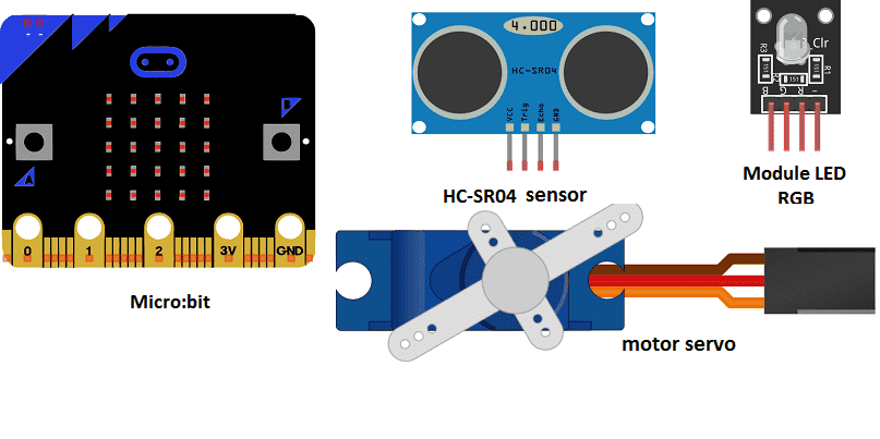
Required components
micro:bit card
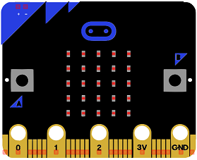
Micro:bit is a small, low-cost microcontroller board that was developed by the Micro:bit Educational Foundation for use in computer education. It is designed to be easy to use and accessible to a wide range of users, including children and beginners. The Micro:bit board measures about 4cm by 5cm and features a 25-pin edge connector, a 5×5 LED matrix, two programmable buttons, an accelerometer, a compass, a Bluetooth Low Energy (BLE) module, and a USB connector.
The Micro:bit is programmed using a variety of programming languages such as Python, JavaScript, and Microsoft Block Editor. It can be used to control a wide range of devices and projects, including robots, drones, lights, and more. The board can be powered by a USB cable or a 3V coin cell battery and can be programmed using a computer or mobile device.
The Micro:bit is widely used in education, providing a hands-on learning experience for students of all ages to learn computer programming, logic, and problem-solving. It’s also used by hobbyist and makers to create fun and interactive projects.
Micro:bit board a GPIO board
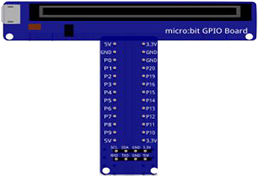
A Micro:bit GPIO (General Purpose Input/Output) Expansion Board is an accessory that can be used to extend the capabilities of a Micro:bit by providing additional input/output (I/O) pins. These pins can be used to connect sensors and actuators, such as LEDs, buttons, motors, and other electronic components.
The expansion board typically connects to the Micro:bit using a standard edge connector and provides a set of male headers that can be used to connect external components.
two HC-SR04 sensors
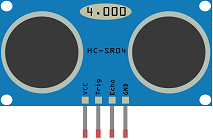
The HC-SR04 is a type of ultrasonic sensor that can be used to detect the presence of objects or measure distance. These sensors work by emitting a high-frequency sound wave and measuring the time it takes for the wave to bounce back after hitting an object. The HC-SR04 sensor can be used in an automatic parking barrier to detect the presence of a vehicle and trigger the barrier to open or close.
In this application, the sensor would be mounted on or near the barrier and programmed to measure the distance to any objects in front of it. When a vehicle is detected by the sensor, the Micro:bit could be programmed to send a signal to the barrier’s motors, causing the barrier to open. Once the vehicle has passed through, the sensor would again measure the distance and send a signal to the motors to close the barrier.
Servomotor
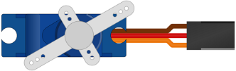
A servo motor is a type of electric motor that can rotate to a specific position, making it well-suited for applications where precise control is needed.
In a servo motor arm barrier, the servo motor is connected to an arm that is used to raise and lower the barrier. The Micro:bit can be programmed to control the servo motor and move the arm to the desired position. For example, when a vehicle is detected by HC-SR04 sensor, the Micro:bit can be programmed to rotate the servo motor and raise the barrier, allowing the vehicle to pass through. Once the vehicle has passed, the Micro:bit can be programmed to lower the barrier again.
RGB LED module
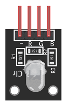
An RGB LED module can be used in an automatic parking barrier to provide visual feedback to the user. An RGB LED module is made up of multiple light-emitting diodes (LEDs) that can produce different colors by varying the intensity of the red, green, and blue elements.
The Micro:bit can be programmed to control the RGB LED module and change the color of the LEDs to indicate the status of the barrier. For example, the Micro:bit could be programmed to turn the LEDs green when the barrier is open and ready to allow a vehicle to pass, red when the barrier is closed and the area is restricted, and yellow when the barrier is in the process of opening or closing. This can help the driver to have a clear understanding of the barrier status, and avoid any confusion.
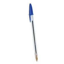
Arm barrier in the form of a pen
connecting wires

Connecting wires are used to connect various components in an electronic circuit. They allow for the transfer of electricity, data, or signals between different devices and components.
When connecting wires to an Arduino or other microcontroller, it is important to pay attention to the correct pinout. The pinout refers to the arrangement of pins on the microcontroller and the corresponding function of each pin. The Arduino pinout can be found in the documentation provided by the manufacturer, or in various resources available online.
test plate

A test plate, also known as a test jig, is a device used to test electronic circuits and components. It is a board or plate that has been designed to hold and connect various components and devices in a specific configuration, allowing for the easy testing and measurement of their performance.
A test plate can be used to test various types of electronic circuits and components, such as microcontrollers, sensors, and actuators. It typically includes connectors and sockets for connecting wires, power supply and measurement devices such as multimeters, oscilloscopes, and power supplies.
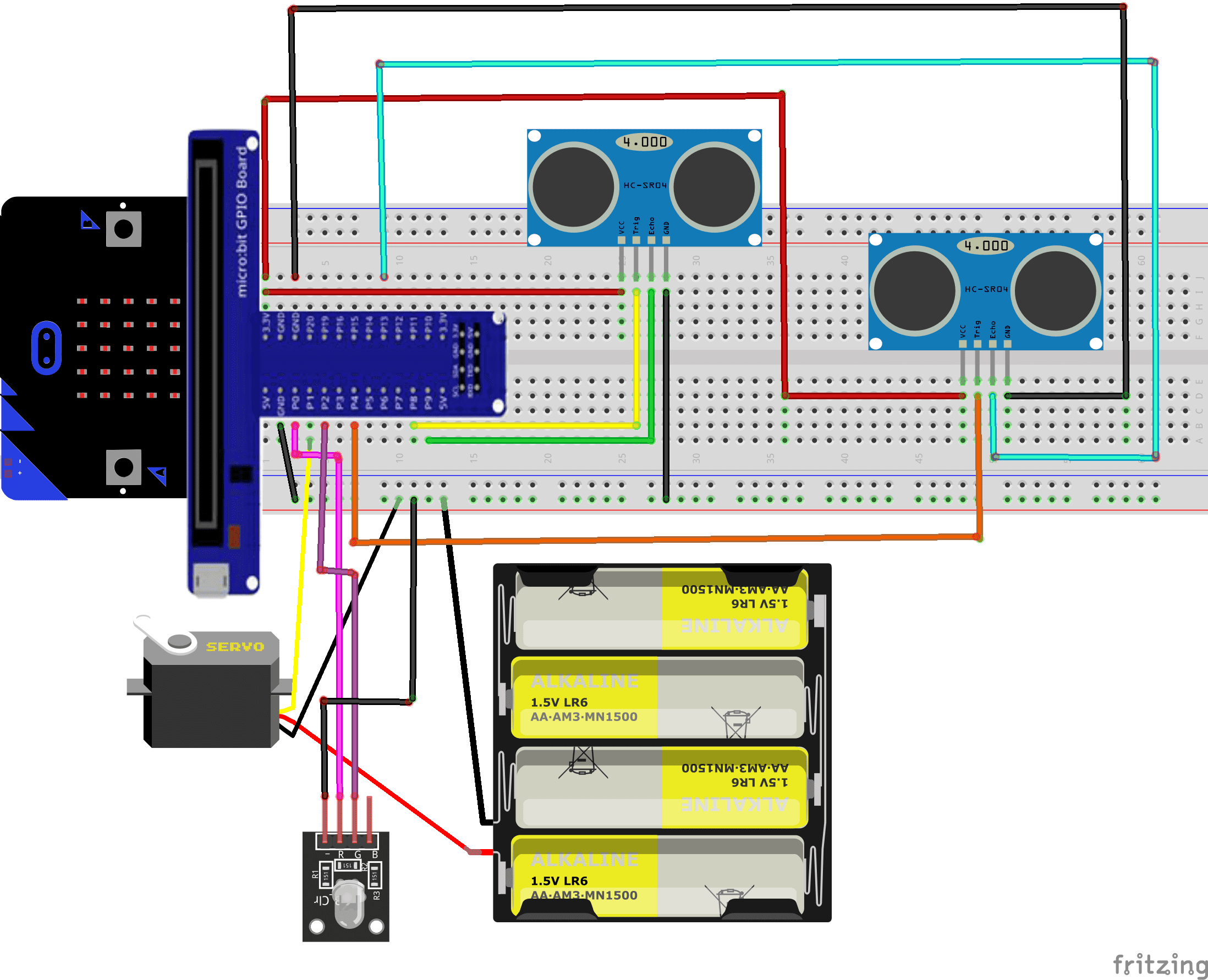
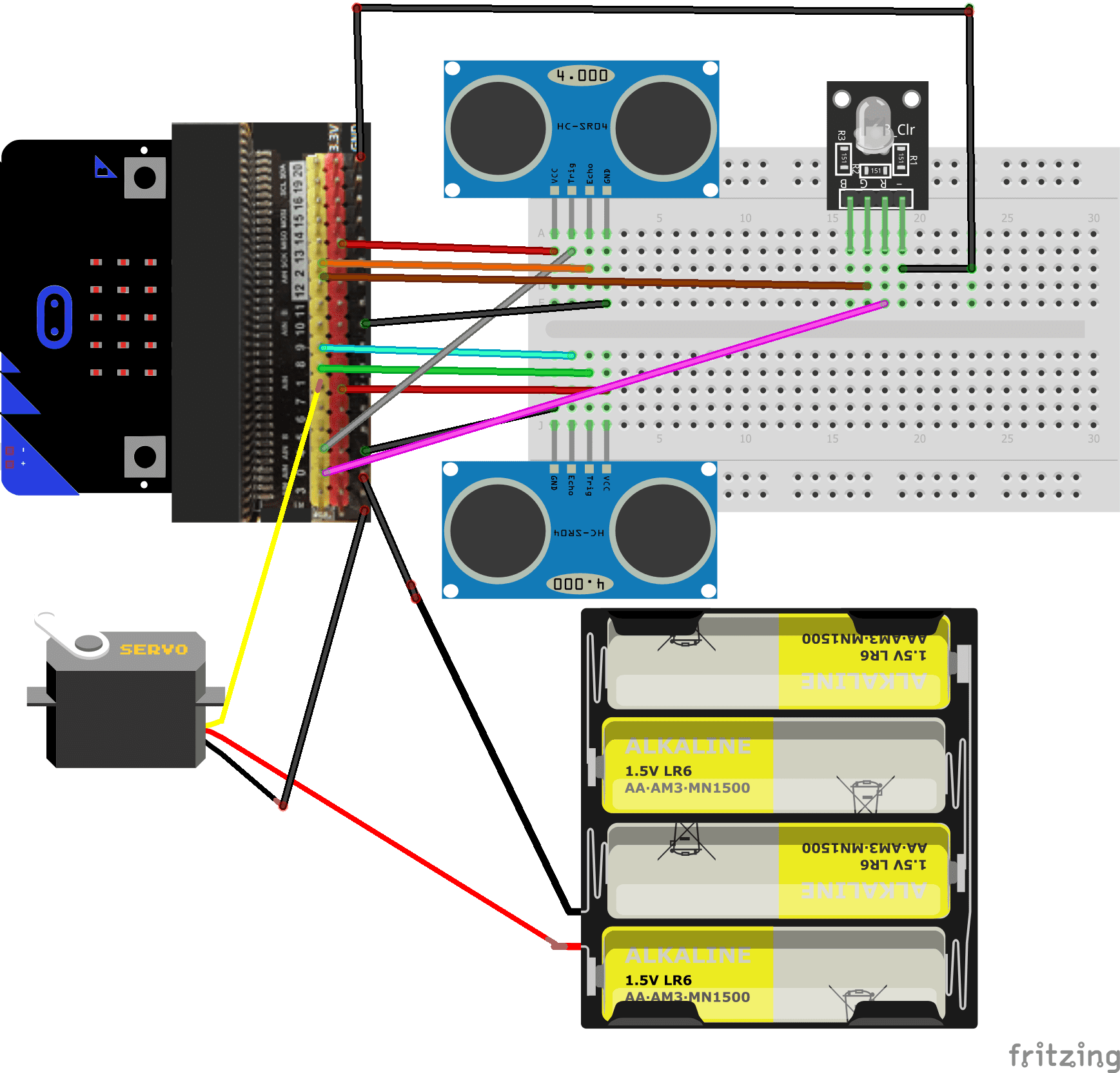
Mounting the Parking
To complete the mounting, you can connect
For the first HC-SR04 sensor:
- the VCC pin to the 3.3V pin of the Micro:bit
- the Trig pin to the P8 pin of the Micro:bit
- the ECHO pin to the P9 pin of the Micro:bit
- the GND pin to the GND pin of the Micro:bit
For the second HC-SR04 sensor:
- the VCC pin to the 3.3V pin of the Micro:bit
- the Trig pin to the P4 pin of the Micro:bit
- the ECHO pin to the P13 pin of the Micro:bit
- the GND pin to the GND pin of the Micro:bit
For the motor servo:
- red wire: power wire to be connected to the terminal(+) of the 4 batteries
- brown wire: wire to be connected to the GND pin of the Micro:bit
- Yellow: positioning signal wire connected to the pin P1 of the Micro:bit
For RGB LED module:
- pin Po from micro:bit to pin (R) for the red color of the RGB LED module
- pin P2 from micro:bit to pin (G) for the green color of the RGB LED module
- pin GND from micro:bit to pin (GND) of the RGB LED module
Mounting 1
Mounting 2
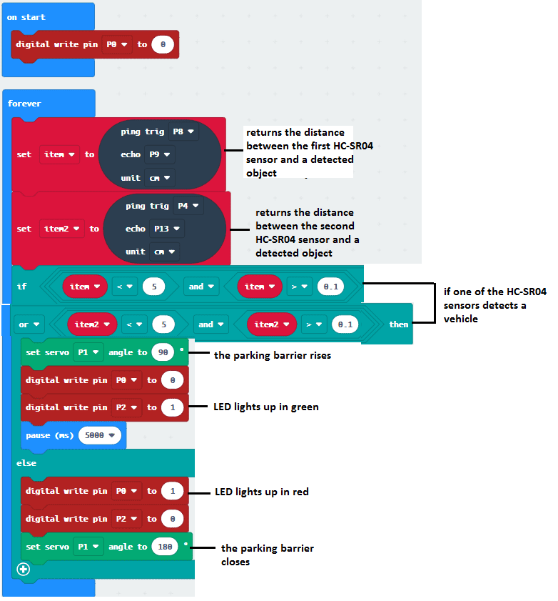
Makecode Program
Here is the Makecode program for the automated parking system:
You can also see

0 commentaire
Leave a comment


Recent tutorials


Most viewed tutorials


Most commented tutorials


Scroll to Top