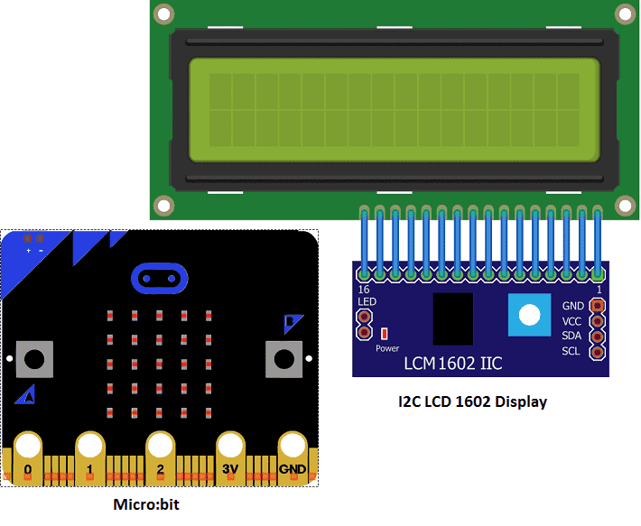
I2C LCD 1602 Display Micro:bit
Create a stopwatch with Micro:bit and LCD display
A stopwatch is a timer device that can be used to measure the amount of time that has elapsed between the start and stop of the timer. Stopwatches can be mechanical, electronic, or software-based.
Purpose of this tutorial:
In this tutorial we will see how to create a stopwatch with the micro:bit card and an LCD display:
- When you press the A button of the Micro:bit, the stopwatch is triggered.
- When the Micro:bit B button is pressed, the stopwatch stops.
Required Components
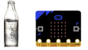
Micro:bit
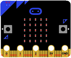
The BBC micro:bit is a small computing device developed by the BBC for use in computer education in the UK. It is a small, self-contained computer with an ARM Cortex-M0 processor, a 5×5 LED matrix, two buttons, and various sensors and input/output (I/O) devices. It is programmed using a web-based code editor and can be used to create a wide variety of interactive projects, such as games, displays, and sensors. The micro:bit is designed to be easy to use and accessible to beginners, with a focus on hands-on, experiential learning. It is also designed to be highly customizable and can be extended using various add-on boards and hardware.
Micro:bit GPIO Board T
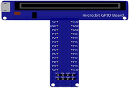
A Micro:bit GPIO board is a type of expansion board that connects to the Micro:bit and provides additional input/output capabilities. They are often used to interface the Micro:bit with external devices such as sensors, actuators, or other electronics. They typically include a set of connectors, such as pins or sockets, that can be used to connect the Micro:bit to external devices, and may also include additional features such as power rails or built-in components. These boards can help to make the development of physical computing projects with the Micro:bit easier and more accessible by providing a variety of connectors and power options.
LDC I2C 16×2 display
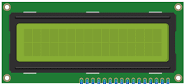
The LDC I2C 16×2 display is a type of LCD display that can display 16 characters in each of its two rows. It is controlled using the I2C protocol, which allows for easy communication with microcontrollers such as the Arduino.
The LDC I2C 16×2 display has a built-in controller called the HD44780, which handles the low-level details of controlling the display. To use the display, you need to send commands and data to the controller over the I2C bus.
To get started with using the LDC I2C 16×2 display, you’ll need to connect it to your microcontroller using the I2C pins. You’ll also need to download a library or write your own code to control the display.
Once you have the display connected and your code running, you can display text on the screen by sending commands and data to the HD44780 controller. For example, you might send a command to move the cursor to a specific location on the screen, and then send data to display text at that location.
connecting wires

Connecting wires are used to connect various components in an electronic circuit. They allow for the transfer of electricity, data, or signals between different devices and components.
When connecting wires to an Arduino or other microcontroller, it is important to pay attention to the correct pinout. The pinout refers to the arrangement of pins on the microcontroller and the corresponding function of each pin. The Arduino pinout can be found in the documentation provided by the manufacturer, or in various resources available online.
test plate

A test plate, also known as a test jig, is a device used to test electronic circuits and components. It is a board or plate that has been designed to hold and connect various components and devices in a specific configuration, allowing for the easy testing and measurement of their performance.
A test plate can be used to test various types of electronic circuits and components, such as microcontrollers, sensors, and actuators. It typically includes connectors and sockets for connecting wires, power supply and measurement devices such as multimeters, oscilloscopes, and power supplies.
Mounting
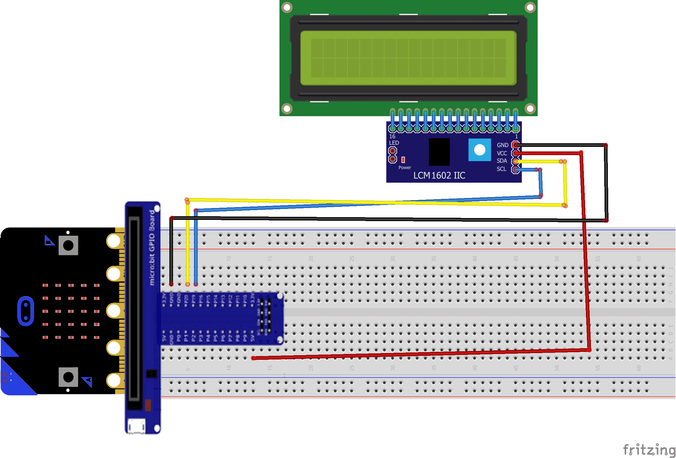
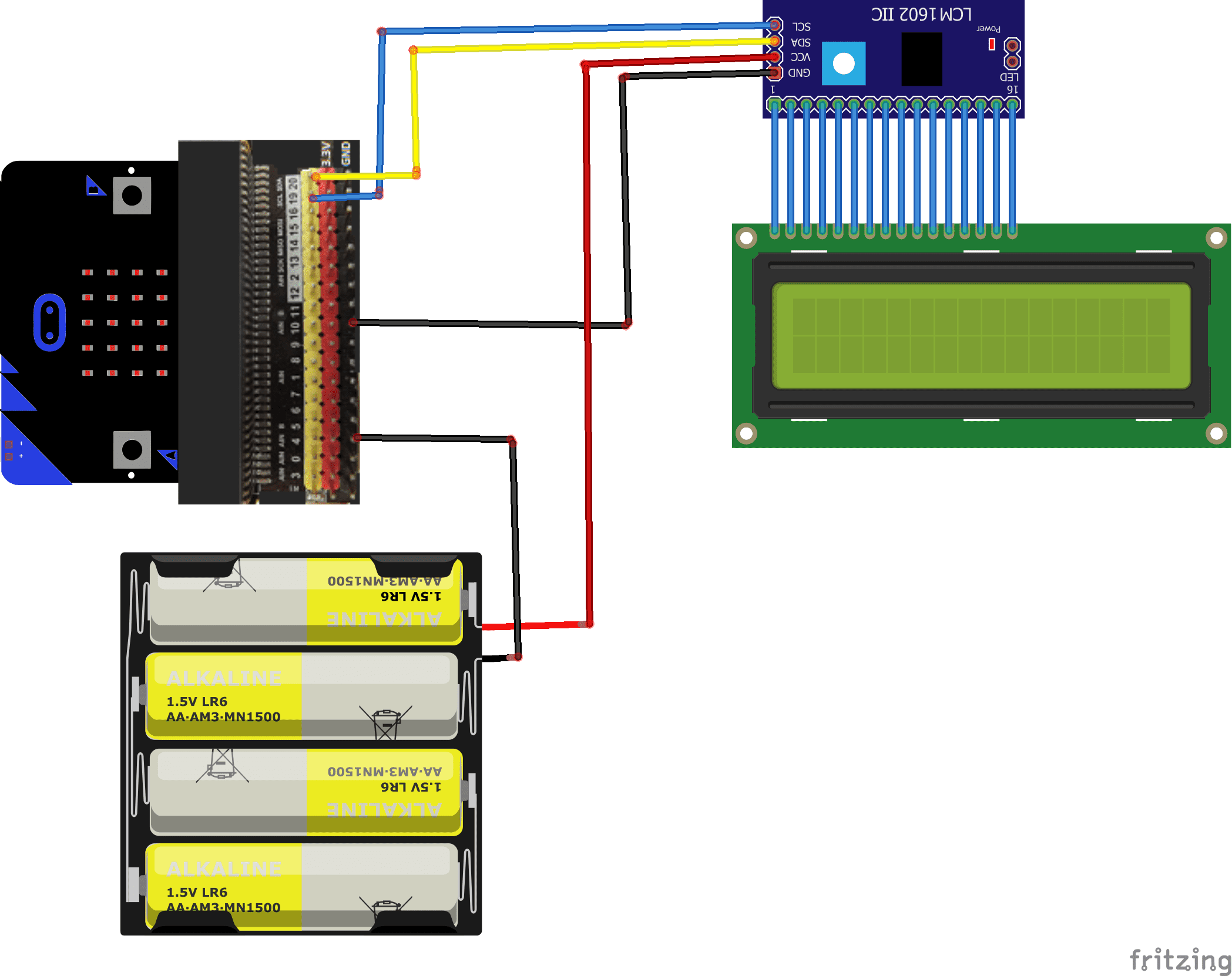
To perform the assembly, connect:
- the VCC pin of the display to an energy of 5V-9V .
- Pin GND from display to pin GND of micro:bit
- Pin SCL from LCD display to pin 19 of micro:bit
- Pin SDA from LCD display to pin 20 of micro:bit
There are several mounting methods.
Mounting (1)
Montage (2)
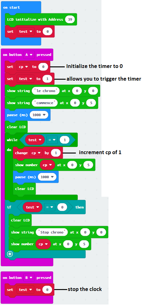
Makecode program
Here is the makecode program that allows you to create a stopwatch and display it on an LCD display.
Note: you must go to Extensions to import the I2c_LCD1602 extension.
You can also see

0 commentaire
Leave a comment


Recent tutorials


Most viewed tutorials


Most commented tutorials


Scroll to Top