App Inventor DC Motor Micro:bit
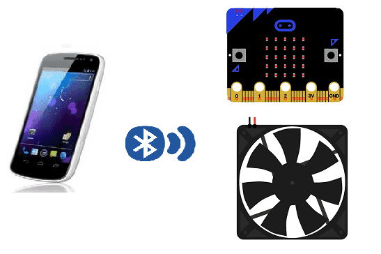
Control a small fan with a smartphone and the Micro:bit
The micro:bit has built-in Bluetooth Low Energy (BLE) capabilities that allow it to connect to other devices, such as smartphones, tablets, and computers. BLE is a wireless technology that is designed for low power consumption and is often used for Internet of Things (IoT) devices and other applications where battery life is a concern.
The micro:bit can be used as a BLE peripheral device, which means it can advertise itself and connect to other devices, such as a smartphone, that act as the central device. Once connected, the micro:bit can send and receive data over the BLE connection.
The micro:bit can be programmed to advertise itself and wait for a connection using the built-in radio module and the micro:bit‘s programming environment, such as the MicroPython or the Microsoft Block Editor. This allows the micro:bit to connect to other BLE-enabled devices and interact with them, such as sending and receiving data and controlling the robot’s motors.
Purpose of this tutorial:
In this tutorial, we will control a small fan by Bluetooth using the Micro:bit card and a smartphone.
we create two programs: a mobile application with App Inventor for the smartphone and a makecode program for the Micro:bit card.
Controlling a small fan with a smartphone and the micro:bit can be done by using a combination of the micro:bit‘s built-in Bluetooth Low Energy (BLE) capabilities and a simple circuit. Here’s an overview of the steps:
- Connect a small fan to the micro:bit‘s general-purpose input/output (GPIO) pins using a transistor as a switch.
- Write a program on the micro:bit that controls the fan‘s speed and direction using the input received from the smartphone via BLE connection.
- Create a mobile application on the smartphone that sends commands to the micro:bit to control the fan‘s speed and direction.
- Pair your smartphone with the micro:bit using the BLE connection.
- Use the mobile app to control the fan‘s speed and direction by sending commands to the micro:bit. The micro:bit receives the commands and uses them to control the fan via the transistor circuit.
Necessary components
Micro:bit
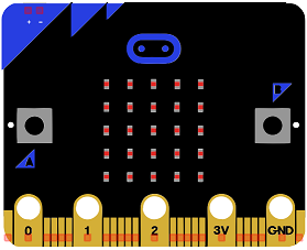
The micro:bit is a small, low-cost computer designed for educational use, particularly in the fields of computer science and engineering. It is about the size of a credit card and can be programmed using a variety of languages, including Python, JavaScript, and Microsoft Block Editor. The device features a small LED matrix display, two buttons, a built-in accelerometer, and a radio module for wireless communication. The micro:bit is intended to be used as a tool for teaching children how to code and how to create their own digital devices and projects.
Micro:bit GPIO Card
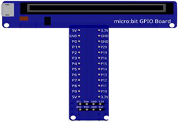
The micro:bit GPIO card is an expansion board for the micro:bit computer that adds additional input and output (I/O) pins, known as General Purpose Input/Output (GPIO) pins. These pins allow the micro:bit to connect to a wide variety of sensors, actuators, and other devices, providing more flexibility and functionality for projects and experiments. The GPIO card typically includes a number of different types of I/O pins, such as digital input/output pins, analog input pins, and PWM (pulse-width modulation) output pins. It also provides a breadboard area to connect electronic components to the micro:bit. With the GPIO card, the micro:bit can be used to control a wide range of devices such as motors, LEDs, sensors and more.
5V Fan
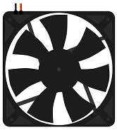
A 5V fan is a type of cooling fan that operates on a 5-volt DC power supply. These fans are commonly used in a variety of electronic devices, such as computers, servers, and other equipment that generates heat. They are also used in DIY projects and hobbyist applications. Because they operate on a lower voltage, they typically consume less power and generate less noise than fans that operate on higher voltages. They are typically smaller in size than other fans. They typically come in the form of a DC motor that spins a rotor with blades. They are connected to the power source with a lead wire and come in different sizes and airflow rates.
Relay
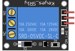
A relay is an electrically operated switch that allows a low power circuit to control a high power circuit. It consists of an electromagnet that, when energized, moves a set of contacts to either make or break an electrical connection. Relays are used in a wide range of applications, such as controlling lights and motors, and providing isolation between different circuits. They are commonly used in automotive, industrial, and home automation systems. The most common types of relays are electromechanical relays (EMRs) and solid-state relays (SSRs). EMRs use an electromagnet to physically move a set of contacts, while SSRs use semiconductor devices such as transistors to switch the current.
The relay is used to turn the fan on and off.
Test plate

A test plate is a type of device used in robotics to test the functionality and performance of various components or systems. It is typically a physical platform or structure that is designed to hold and support various test items or devices, such as sensors, actuators, motors, or other types of mechanical or electrical components. Test plates can be used to simulate different environments or conditions, such as temperature, humidity, vibration, or other factors, in order to evaluate the performance of the components or systems being tested. They can also be used to perform a variety of diagnostic or diagnostic tests, such as stress testing, endurance testing, or other types of evaluations.
Connecting wires

Wires are used to transmit electrical signals and power to various components such as motors, sensors, and microcontrollers. It’s important to properly route and secure the wires to prevent tangles and damage. There are several methods for doing this, including using cable ties, clamps, and wire looms. It’s also a good idea to use different colors or labeling to identify the different wires and their functions. When connecting wires in a robot, it’s important to follow proper safety procedures, such as using the correct wire stripper and connectors, and wearing protective equipment such as gloves and safety glasses.
Mounting
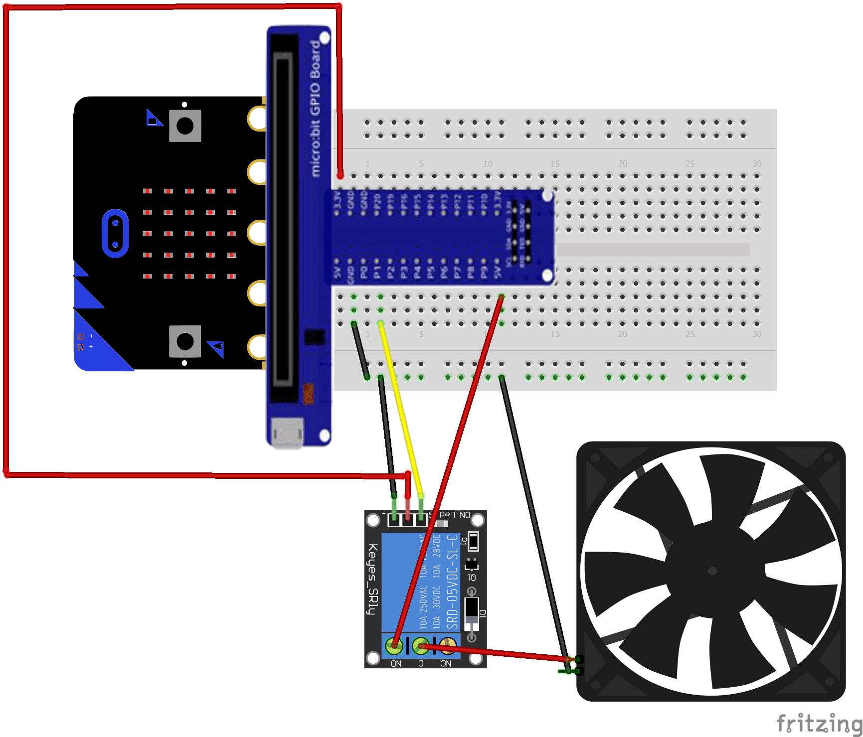
To build the assembly we can connect:
Relay:
- pin S to pin P1 of micro:bit
- pin (-) to GND pin of micro:bit
- pin (+) to 3.3V pin of micro:bit
- pin ON to 5v energy
Fan:
-
the first terminal to the COM pin of the relay
-
the second terminal to the GND terminal of the Micro:bit card
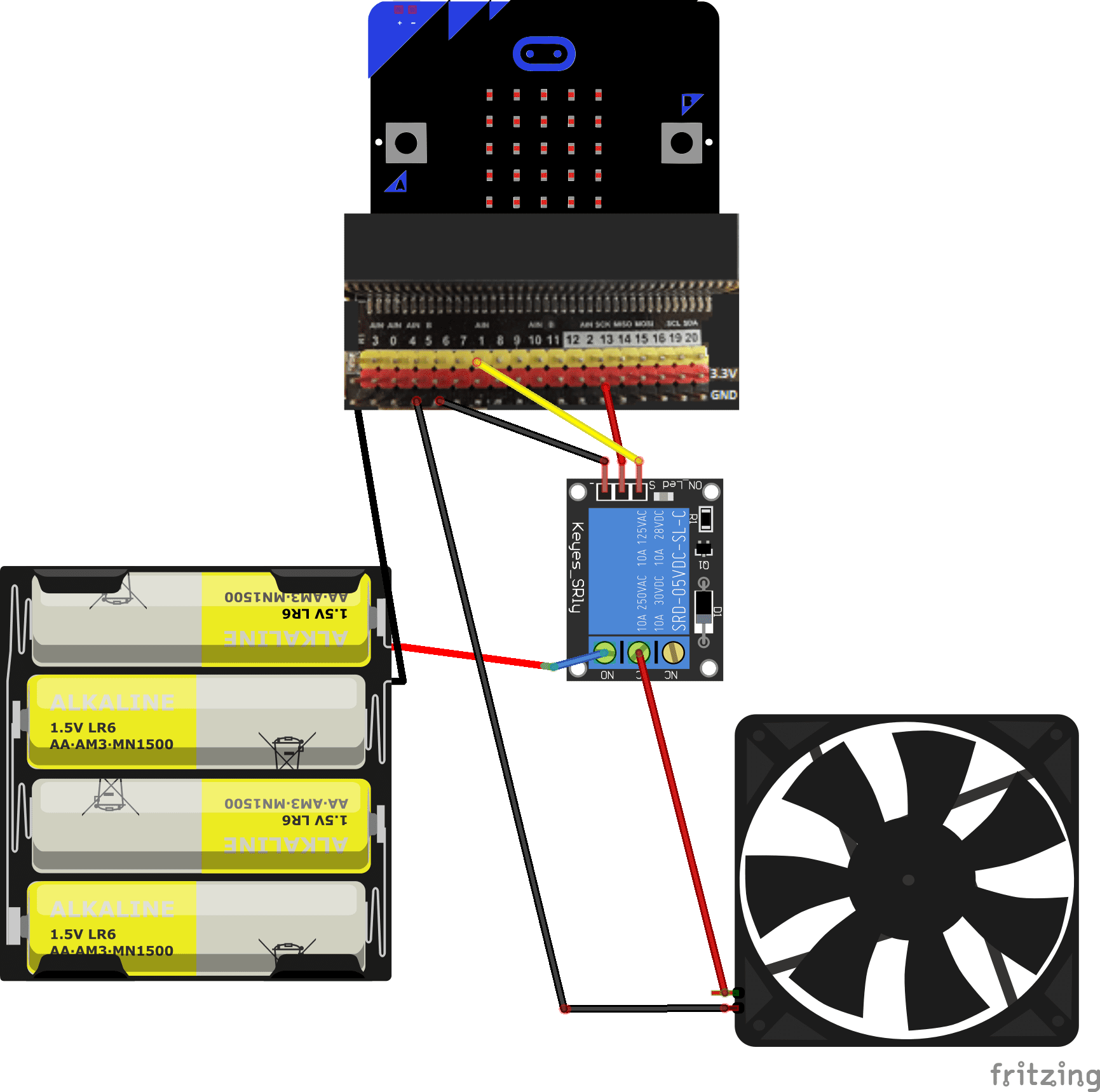
There are many mounting methods and here are some examples:
Mounting 1
Mounting 2
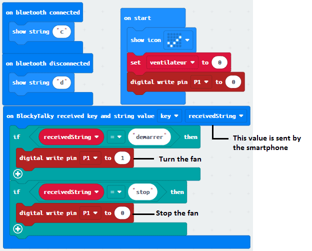
Makecode program
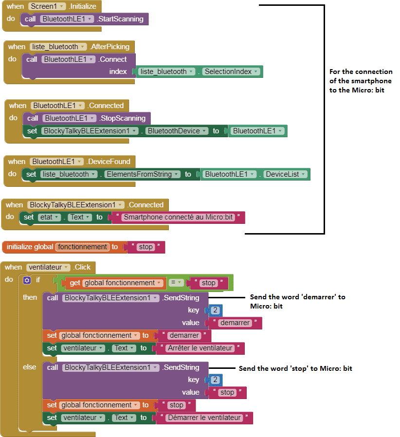
Here is the makecode program which allows you to connect the Micro: bit card to the smartphone and to receive a message containing the order to start or stop the fan.
Creation of the application with App Inventor:
We create a mobile application named ‘start_ventilator’ with App Inventor which allows remote control of the fan.
We propose to create the design of the application, with the following visual:
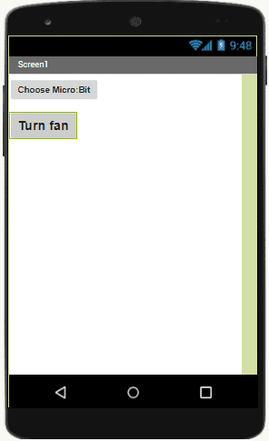
Programming with App Inventor
To program the application, App Inventor offers us to use the Blocks space, which allows you to create a program in the form of a block diagram. Very easy to use but requiring a little programming logic.
Here is the program of the application created in the Blocks area of the Inventor App:
You can also see

0 commentaire
Leave a comment


Recent tutorials


Most viewed tutorials


Most commented tutorials


Scroll to Top