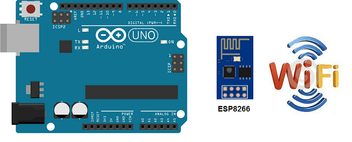
Arduino UNO and ESP8266 are two popular microcontrollers used in DIY electronics and IoT projects. The Arduino UNO is a microcontroller board based on the ATmega328P chip, while the ESP8266 is a WiFi module with an integrated microcontroller.
One of the main advantages of using the ESP8266 with an Arduino UNO is that it allows the Arduino to connect to a WiFi network and communicate over the internet. This makes it possible to create IoT projects that can be controlled and monitored remotely.
Purpose of this tutorial
The purpose of connecting Arduino UNO to the Wi-Fi network using the ESP8266 module is to allow the Arduino to connect to the internet and communicate with other devices connected to the network. This can be useful for many projects, such as collecting data from sensors and sending it to a remote server for processing, controlling an embedded system remotely, or creating a smart home automation system.
The necessary components
Arduino UNO
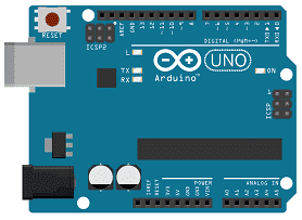
Arduino UNO is a popular microcontroller board based on the ATmega328P microcontroller chip. It was developed by Arduino, an open-source hardware and software community, and released in 2010. The board is designed to be easy to use, making it a popular choice for beginners and hobbyists who want to learn about electronics and programming.
The Arduino UNO board has 14 digital input/output pins, 6 analog inputs, a 16 MHz quartz crystal, a USB connection, a power jack, and an ICSP header for programming the board with an external programmer. The board also has a built-in LED connected to pin 13, which can be used for testing and debugging.
One of the key features of the Arduino UNO is its simplicity and ease of use. The board can be programmed using the Arduino Integrated Development Environment (IDE), a free software tool that allows users to write, compile, and upload code to the board. The IDE includes a library of pre-written code and examples that can be used to get started quickly.
The Arduino UNO board can be used for a wide range of projects, from simple LED blink programs to more complex projects such as robots, home automation systems, and Internet of Things (IoT) devices. It is also compatible with a wide range of sensors and other electronic components, making it easy to build custom projects.
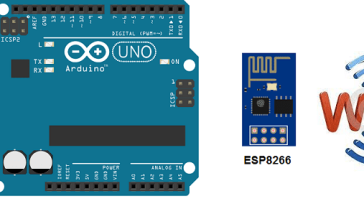
ESP8266 Module
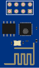
ESP8266 is a low-cost, WiFi-enabled microcontroller module with an integrated TCP/IP protocol stack. The module was developed by Espressif Systems, a Chinese company, and released in 2014. Since its release, the ESP8266 module has become very popular in the maker community due to its low cost and ease of use.
The ESP8266 module is based on the ESP8266EX chip, which includes a 32-bit RISC CPU, a Wi-Fi transceiver, and a 10-bit ADC. The module supports both 802.11b/g/n Wi-Fi protocols and can be used as a standalone module or integrated into other systems.
The module can be programmed using the Arduino IDE or other programming tools such as Lua, Python, and C. It also supports OTA (over-the-air) updates, which allows users to update the firmware wirelessly.
The ESP8266 module is commonly used in Internet of Things (IoT) projects, where it can be used to connect sensors and other devices to the internet. It can also be used in home automation systems, smart lighting systems, and other projects that require wireless connectivity.
LCD I2C 16×2 Display
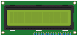
The LCD I2C 16×2 Display is a commonly used module in electronic projects for displaying information. The module consists of a 16×2 character LCD (liquid crystal display) and an I2C (Inter-Integrated Circuit) interface module that allows it to be controlled with just two wires, making it easy to integrate into projects.
The 16×2 character LCD display can display up to 16 characters on two rows. It is commonly used to display sensor data, messages, or other information in projects. The display can be controlled using a variety of microcontrollers, including the Arduino UNO and ESP8266.
The I2C interface module allows the display to be controlled with just two wires: SDA (serial data) and SCL (serial clock). This makes it easy to connect the display to a microcontroller, as it requires fewer pins and wiring than a traditional parallel interface. The I2C interface module also includes a potentiometer for adjusting the contrast of the display.
To use the LCD I2C 16×2 Display, you will need to download and install the LiquidCrystal_I2C library in the Arduino IDE. Once installed, you can use the library to control the display and display information on the screen.
3.3V/5V power module
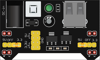
A 3.3V/5V power module is a voltage regulator module that allows you to convert a higher voltage to a lower voltage. The module typically accepts a voltage input of around 6V to 24V and outputs a regulated voltage of either 3.3V or 5V, depending on the module.
The 3.3V/5V power module is commonly used in electronic projects to power microcontrollers, sensors, and other components that require a regulated voltage. For example, the ESP8266 module requires a regulated voltage of 3.3V, while the Arduino UNO can be powered by either 3.3V or 5V depending on the project requirements.
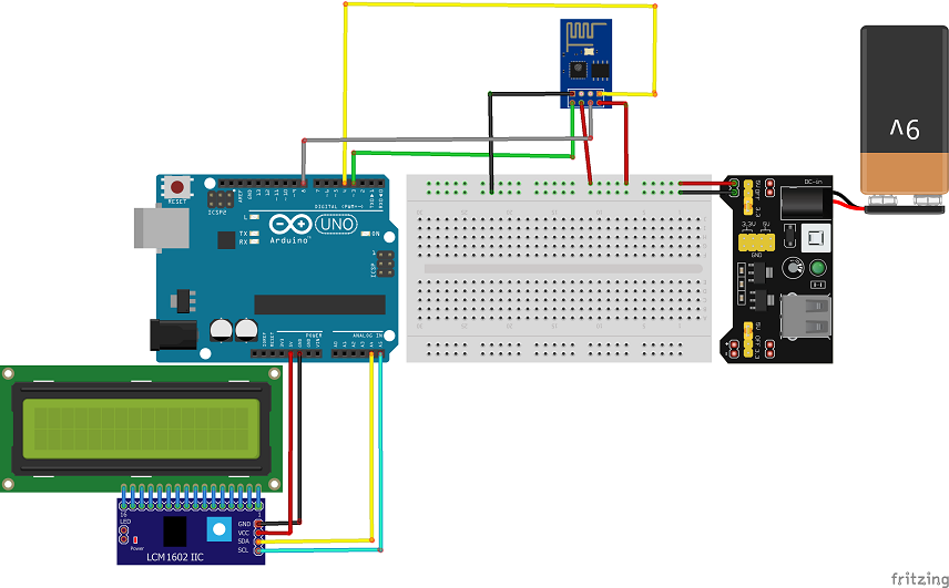
Assembly
The ESP8266 module is connected to the Arduino UNO using the following pins:
- ESP8266 RX –> Arduino UNO (pin 3)
- ESP8266 TX –> Arduino UNO (pin 4)
- ESP8266 RST –> Arduino UNO (pin 8)
- ESP8266 VCC –> power module (5V)
- ESP8266 GND –> power module (GND=
To use the I2C 16×2 LCD display with an Arduino, you can follow these steps:
-
Connect the SDA wire from the I2C LCD display to pin A4 of the Arduino.
-
Connect the SCL wire from the I2C LCD display to pin A5 of the Arduino.
-
Connect the VCC wire of the I2C LCD display to a 5V power source.
-
Connect the GND wire of the I2C LCD display to the ground of the Arduino.
Arduino program
Load the following sketch (program) on your Arduino UNO to connect to the WIFI network with the ESP8266 module:
We must use these two libraries: Adafruit_ESP8266 et LiquidCrystal_I2C
|
1 2 3 4 5 6 7 8 9 10 11 12 13 14 15 16 17 18 19 20 21 22 23 24 25 26 27 28 29 30 31 32 33 34 35 36 37 38 39 40 41 42 43 44 45 46 47 48 49 50 51 52 53 54 55 56 57 58 59 60 61 62 63 64 65 66 67 68 69 70 71 72 73 74 75 76 77 78 79 80 81 82 83 84 85 86 87 88 89 90 91 92 93 94 |
#include <Adafruit_ESP8266.h> #include <SoftwareSerial.h> #include <LiquidCrystal_I2C.h> #define ESP_RX 3 #define ESP_TX 4 #define ESP_RST 8 SoftwareSerial softser(ESP_RX, ESP_TX); LiquidCrystal_I2C lcd(0x27, 20, 4); // Must declare output stream before Adafruit_ESP8266 constructor; can be // a SoftwareSerial stream, or Serial/Serial1/etc. for UART. Adafruit_ESP8266 wifi(&softser, &Serial, ESP_RST); // Must call begin() on the stream(s) before using Adafruit_ESP8266 object. #define ESP_SSID "HUAWEI Y5 2019" // Your network name here #define ESP_PASS "b582058c4d86" // Your network password here #define PORT 80 // Find/Google your email provider's SMTP outgoing port for unencrypted email int count = 0; // we'll use this int to keep track of which command we need to send next bool send_flag = false; // we'll use this flag to know when to send the email commands void setup() { lcd.init(); char buffer[50]; // This might work with other firmware versions (no guarantees) // by providing a string to ID the tail end of the boot message: // comment/replace this if you are using something other than v 0.9.2.4! wifi.setBootMarker(F("Version:0.9.2.4]\r\n\r\nready")); softser.begin(9600); // Soft serial connection to ESP8266 Serial.begin(57600); while(!Serial); // UART serial debug // Test if module is ready lcd.backlight(); Serial.print(F("Hard reset...")); lcd.print(F("Hard reset...")); if(!wifi.hardReset()) { Serial.println(F("no response from module.")); for(;;); } Serial.println(F("OK.")); lcd.print(F("OK.")); Serial.print(F("Soft reset...")); lcd.print(F("Soft reset...")); if(!wifi.softReset()) { Serial.println(F("no response from module.")); for(;;); } Serial.println(F("OK.")); lcd.clear(); lcd.print(F("OK.")); Serial.print(F("Checking firmware version...")); lcd.clear(); lcd.print(F("Checking firmware version...")); delay(2000); wifi.println(F("AT+GMR")); if(wifi.readLine(buffer, sizeof(buffer))) { Serial.println(buffer); lcd.clear(); lcd.print(buffer); delay(2000); wifi.find(); // Discard the 'OK' that follows } else { Serial.println(F("error")); } Serial.print(F("Connecting to WiFi...")); lcd.clear(); lcd.print(F("Connect to WiFi...")); delay(2000); if(wifi.connectToAP(F(ESP_SSID), F(ESP_PASS))) { // The ESP8266 wifi module is connected to the network // IP addr check isn't part of library yet, but // we can manually request and place in a string. Serial.print(F("OK\nChecking IP addr...")); wifi.println(F("AT+CIFSR")); if(wifi.readLine(buffer, sizeof(buffer))) { lcd.clear(); Serial.println(buffer); // show ip address of wifi module ESP8266 lcd.setCursor(0, 0); lcd.print("IP de ESP8266 "); lcd.setCursor(0, 1); lcd.print(buffer); } } } void loop() { } |
You can also see

1 commentaire
Leave a comment


Recent tutorials


Most viewed tutorials


Most commented tutorials


Scroll to Top
MIRKO 11-06-2323
I followed the tutorial step by step but the serial monitor keeps giving me back "no response from module. what could be the problem?"