Presentation of robot car
A robot car is a type of autonomous vehicle that is equipped with various sensors, actuators, and a computer or microcontroller to allow it to move and perform tasks without human intervention. Robot cars can be used for a variety of purposes, including transportation, scientific research, and entertainment.
Robot cars typically use a combination of sensors, such as cameras, lidars, radars, and ultrasonic sensors, to gather information about their surroundings. This information is then processed by the robot‘s computer or microcontroller, which determines the appropriate actions to take based on the information received. The robot car can then use actuators, such as motors, to control its movement and perform tasks.
Robot cars can be powered by a variety of sources, including batteries, gasoline, or electricity. They can also be equipped with various types of propulsion systems, such as wheels or tracks, to help them move on different types of terrain.
Robot cars can be designed for a variety of applications, including personal transportation, military missions, search and rescue operations, and delivery services. Some of the most advanced robot cars are even capable of driving themselves on public roads, although the use of autonomous vehicles for personal transportation is still a developing technology and is subject to various legal and regulatory restrictions.
Presentation of obstacle avoiding robot
An obstacle avoiding robot is a type of robot that is designed to navigate through its environment while avoiding obstacles that are in its path. This type of robot is equipped with sensors, such as ultrasound or infrared sensors, that allow it to detect obstacles and make decisions about how to navigate around them.
Obstacle avoiding robots are often used for educational purposes, as a demonstration of basic robotics principles, and as a platform for experimenting and innovating. They can also be used for practical purposes, such as cleaning floors or navigating through hazardous environments.
To build an obstacle avoiding robot, you typically need to start with a base platform, such as a two-wheeled or four-wheeled chassis. You will then need to add the necessary components, such as motors, a microcontroller or single-board computer, and the appropriate sensors.
Once the robot is assembled, you can program it to perform a variety of tasks, such as following a line, avoiding obstacles, or responding to signals from a remote control. You can also experiment with different types of sensors, actuators, and control algorithms to see how they impact the robot‘s behavior.
Presentation of obstacle avoiding robot using ESP32
It is possible to build an obstacle avoiding robot using an ESP32 microcontroller. The ESP32 is a popular microcontroller that is well suited for robotics projects due to its compact size, low power consumption, and high performance.
To build an obstacle avoiding robot using an ESP32, you will need to start by assembling a chassis for the robot and mounting the ESP32 on it. You will then need to connect the ESP32 to a set of sensors, such as HC-SR04 sensor, that will allow the robot to detect obstacles.
Next, you will need to write the software that will control the robot. This software will need to use the information from the sensors to determine the best way to navigate around obstacles and control the motors to move the robot.
One popular programming environment for the ESP32 is the Arduino Integrated Development Environment (IDE). The Arduino IDE provides a user-friendly interface and a large library of pre-written code, making it a great choice for beginners.
Once your robot is assembled and the software is written, you can test the robot to see how well it performs in avoiding obstacles. You may need to fine-tune the code or adjust the sensor settings to get the best performance.
Obstacle avoiding robot using ESP32 operation
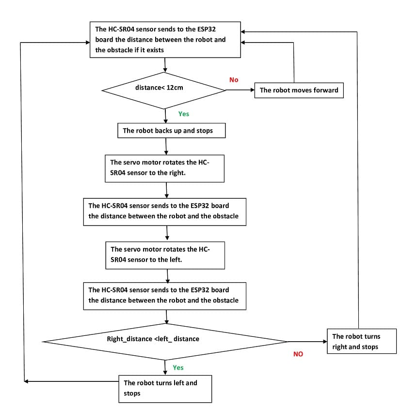
The operation of an obstacle avoiding robot using an ESP32 microcontroller involves several key steps:
- Sensing: The robot uses a HC-SR04 sensor, to detect obstacles in its environment. The sensor readings are then transmitted to the ESP32 microcontroller.
- Processing: The ESP32 microcontroller processes the sensor data and determines the best way to navigate around the obstacles. This typically involves using algorithms to determine the distance and direction of the obstacles and deciding the best way to move the robot.
- Actuation: Based on the processing results, the ESP32 microcontroller sends signals to the robot‘s actuators, such as motors or servos, to control its movement. The robot moves in response to these signals and avoids the obstacles in its path.
- Feedback: The robot continues to sense its environment and adjust its movement based on the sensor data. This feedback loop allows the robot to continuously improve its performance and avoid obstacles more effectively over time.
The necessary components
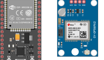
ESP32 card
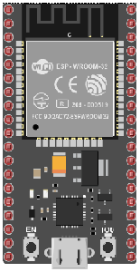
ESP32 is a low-cost, low-power microcontroller that is designed for use in a variety of Internet of Things (IoT) applications. It is a popular choice for makers, hobbyists, and professionals due to its compact size, high performance, and support for a wide range of peripherals and protocols.
The ESP32 card is a small, standalone module that contains the ESP32 microcontroller and associated components, such as memory, Wi-Fi, and Bluetooth connectivity. The card is designed to be easy to use and integrate into a variety of projects, including robots, home automation systems, and IoT devices.
To use the ESP32 card, you simply need to connect it to your computer or other development platform and write the code that will run on the microcontroller. The ESP32 supports several programming environments, including the Arduino Integrated Development Environment (IDE) and the Espressif IoT Development Framework (IDF).
L298N Module
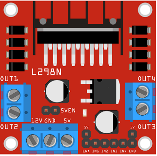
The L298N module is a type of dual H-bridge motor driver. It is commonly used to control the speed and direction of two DC motors, or to control one stepper motor. The module is based on the L298 motor driver IC, which is a dual full-bridge driver designed to drive inductive loads such as relays, solenoids, DC and stepping motors.
The L298N module can handle high current loads, up to 2A per channel and 4A maximum, making it suitable for a wide range of applications. It also has built-in protection against overheating, over-current, and short-circuits, which helps to ensure the longevity of the module and the connected devices.
The module can be controlled using a microcontroller, such as an Arduino board, through pulse-width modulation (PWM) or direction control signals. This makes it a popular choice for various robotics, automation, and DIY projects.
HC-SR04 sensor
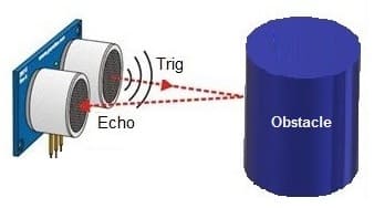
The HC-SR04 is a type of ultrasonic sensor that is commonly used for distance measurement and object detection. The sensor uses sound waves to determine the distance to an object by measuring the time it takes for an ultrasound signal to travel from the sensor to the object and back.
The HC-SR04 sensor consists of two main components: a transmitting unit (the “trigger”) and a receiving unit (the “echo”). The trigger sends out a short ultrasonic pulse, and the echo receives the reflected pulse from an object. By measuring the time between the trigger and the echo, the sensor can calculate the distance to the object.
The HC-SR04 sensor can be used in a wide range of applications, including obstacle avoidance in robotics, distance sensing in automation, and proximity detection in security systems. The sensor is relatively easy to use and can be interfaced with microcontrollers such as the Arduino, making it a popular choice for DIY projects.
The sensor can measure distances between 2 cm and 400 cm, with a typical accuracy of 3mm. It is important to keep in mind that the accuracy of the measurements can be affected by factors such as the reflectivity of the objects and the presence of ambient noise.
Servo motor

A servo motor is a type of motor that is commonly used in control systems for precise positioning of mechanical parts. Servo motors are equipped with a control circuit and a position-sensing device, such as a potentiometer, that allows them to rotate to a specific angle and hold that position.
Servo motors are typically controlled using pulse width modulation (PWM) signals. The duration of the pulse, also known as the pulse width, determines the position of the motor. By controlling the pulse width, the control circuit can rotate the motor to a specific angle and hold it in place.
Servo motors are commonly used in applications such as robotic arms, camera gimbals, and RC toys. They are also used in industrial automation systems for precise control of machine parts and processes.
A servo motor can be used to pivot an HC-SR04 sensor, allowing the robot to scan its surroundings and detect obstacles in different directions. The servo motor can be attached to the HC-SR04 sensor and controlled by the microcontroller to change its orientation.
5V DC motor
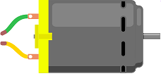
A 5V DC motor is a type of direct current (DC) motor that operates on 5 volts of power. DC motors are commonly used in a variety of applications, including robotics, toys, and small appliances.
The 5V DC motor typically has two terminals: one for the positive voltage and one for the negative voltage. When the voltage is applied to the terminals, the motor will start to rotate. The direction of rotation and the speed of the motor can be controlled by reversing the polarity of the voltage applied to the terminals.
5V DC motors are often used in small and lightweight applications due to their low power consumption and small size. However, they typically have lower torque and speed compared to higher voltage DC motors, making them less suitable for applications that require a lot of power or speed.
9V Battery
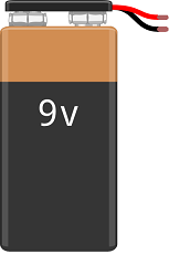
A 9V battery is a type of rectangular, cylindrical battery that is commonly used in a variety of portable devices and electronics. It is commonly referred to as a “transistor battery” because it was originally designed for use in transistor radios.
9V batteries have a nominal voltage of 9 volts and are made up of six individual 1.5V cells connected in series. They are often used in devices that require a compact and portable power source, such as smoke detectors, portable radios, and handheld games.
Fils de connexion

Connecting wires are electrical wires used to connect various electrical components in a circuit. They are an essential component of any electrical or electronic system, as they are used to transfer electrical energy and signals between the different parts of the circuit.
2 wheel car robot kit
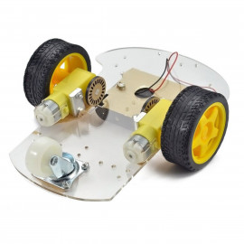
A 2 wheel car robot kit is a kit designed to help you build a small, two-wheeled robot. The kit typically includes all of the components you need to assemble the robot, such as wheels, motors, a microcontroller, a battery, and a set of sensors and actuators.
These kits are often used for educational purposes, to teach individuals about robotics and electronics. They can also be used for hobby projects and as a platform for experimentation and innovation.
The exact components included in a 2 wheel car robot kit can vary, but they typically include a microcontroller or single-board computer, such as an Arduino or Raspberry Pi, a pair of DC motors, wheels, and a battery for power. The kit may also include additional components such as sensors, such as infrared or ultrasonic sensors, and actuators, such as LEDs or buzzers.
To build the robot, you typically need to follow a set of instructions and assemble the components according to the design provided. Once the robot is assembled, you can program it to perform a variety of tasks, such as following a line, avoiding obstacles, or responding to signals from a remote control.
Overall, 2 wheel car robot kits are a fun and educational way to learn about robotics and electronics. Whether you are a beginner or an experienced hobbyist, these kits can provide you with a fun and engaging platform for exploring the world of robotics.
Pour assembler les composants du kit robot, vous pouvez voir cette vidéo.
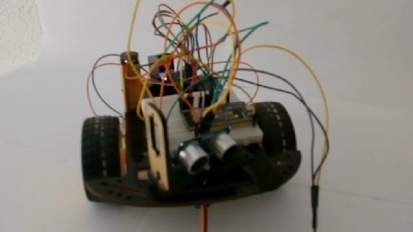
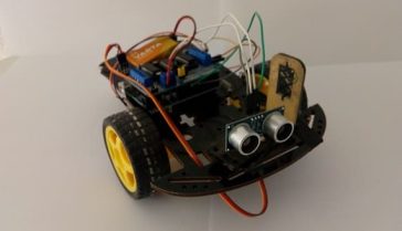
Assembly of the robot
A robot car that uses an L298N module as a motor driver can be a fun and educational project. Here is an overview of the basic components and steps involved in building such a robot car:
Components:
- Chassis: This can be a plastic or metal base that will hold all the other components of the robot car.
- Motors: Two DC motors are typically used to drive the robot car, one for each wheel.
- Wheels: The robot car will need wheels that can be attached to the motors.
- L298N module: This will control the speed and direction of the motors.
- Microcontroller: An Arduino board is a common choice for this, as it can easily interface with the L298N module and be programmed to control the robot car.
- Battery: A battery is needed to provide power to the motors and the microcontroller.
- Other components: Depending on the specific requirements of the project, other components such as sensors, LEDs, and a Bluetooth module may be added.
Steps:
- Assemble the chassis and attach the motors to it.
- Connect the motors to the L298N module.
- Connect the L298N module to the microcontroller.
- Write the code to control the robot car using the microcontroller and upload it to the board.
- Attach the battery to the robot car and test it.
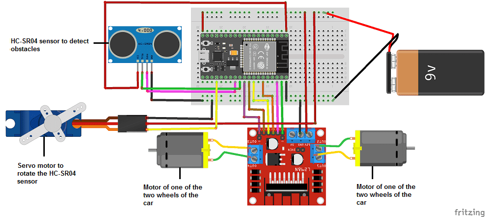
1- For module L298N
-
Connect pin N°23 of the ESP32 board to the ENA pin of the L298N module.
-
Connect pin N°22 of the ESP32 board to pin IN1 of the L298N module.
-
Connect pin N°21 of the ESP32 board to pin IN2 of the L298N module.
-
Connect pin N°19 of the ESP32 board to pin IN3 of the L298N module.
-
Connect pin N°18 of the ESP32 board to pin IN4 of the L298N module.
-
Connect pin N°5 of the ESP32 board to the ENB pin of the L298N module.
-
Connect the GND pin of the ESP32 board to the GND pin of the L298N module.
-
Connect the 5V pin of the ESP32 board to the (+) pin of the 9V battery
-
Connect the GND pin of the ESP32 board to the (-) terminal of the 9V battery
-
Connect the 12V pin of the L298N module to the (+) pin of the 9V battery
-
Connect the two motors of the car to the L298N board
2- For the HC-SR04 sensor we connect
-
The GND terminal of the sensor to the GND pin of the ESP32 board
-
The VCC terminal of the sensor to the 3.3V pin of the ESP32 board
-
The ECHO terminal of the sensor to pin N°16 of the ESP32 board
-
The TRIG terminal of the sensor to pin N°17 of the ESP32 board
3- For the servo motor we connect
-
We connect the red wire of the servomotor to the terminal (+) of the 9V battery
-
We connect the brown wire of the servo motor to the GND pin of the ESP32 board
-
We connect the red wire of the servomotor to pin N°15 of the ESP32 board
Micropython program
Here is the robot program controlled by the ESP32 board that detects and avoids obstacles using HC-SR04 sensor.
You have to import these two libraries : hcsr04 and DCMotor
|
1 2 3 4 5 6 7 8 9 10 11 12 13 14 15 16 17 18 19 20 21 22 23 24 25 26 27 28 29 30 31 32 33 34 35 36 37 38 39 40 41 42 43 44 45 46 47 48 49 50 51 52 53 54 55 56 57 58 59 60 61 62 63 64 65 |
from hcsr04 import HCSR04 from DCMotor import DCMotor import machine from machine import Pin, PWM import time from time import sleep frequency = 15000 # Connect the ESP32 board to the L298N module pin1 = Pin(22, Pin.OUT) pin2 = Pin(21, Pin.OUT) pin3 = Pin(19, Pin.OUT) pin4 = Pin(18, Pin.OUT) enable = PWM(Pin(23), frequency) enable1 = PWM(Pin(5), frequency) dc_motor = DCMotor(pin1, pin2, enable) dc_motor = DCMotor(pin1, pin2, enable, 350, 1023) dc_motor1 = DCMotor(pin3, pin4, enable1) dc_motor1 = DCMotor(pin3, pin4, enable1, 350, 1023) # Connect the servo motor to the ESP32 board p15 = machine.Pin(15) servo = machine.PWM(p15,freq=50) servo.duty(70) # Connect the HC-SR04 sensor to the ESP32 board sensor = HCSR04(trigger_pin=17,echo_pin=16,echo_timeout_us=1000000) while True: distance = sensor.distance_cm() print(distance,' cm') if (distance<20): # if the HC-SR04 sensor detects an obstacle dc_motor.stop() # the robot car stops dc_motor1.stop() time.sleep_ms(1000) dc_motor.backwards(100) # the robot car backs up dc_motor1.backwards(100) time.sleep_ms(1000) dc_motor.stop() # the robot car stops dc_motor1.stop() time.sleep_ms(1000) for x in range(70,20,-1):# turn the HC-SR04 sensor to the right servo.duty(x) time.sleep_ms(50) distance_droite = sensor.distance_cm() time.sleep_ms(100) for x in range(20,110): # turn the HC-SR04 sensor to the left servo.duty(x) time.sleep_ms(50) distance_gauche = sensor.distance_cm() time.sleep_ms(1000) for x in range(110,70,-1): servo.duty(x) time.sleep_ms(100) if (distance_gauche < distance_droite) : # compare the two distances to choose the right direction dc_motor1.forward(100) # the robot car turns right time.sleep_ms(1000) dc_motor1.stop() time.sleep_ms(500) else: dc_motor.forward(100) # the robot car turn left time.sleep_ms(1000) dc_motor.stop() time.sleep_ms(500) else: dc_motor.forward(100) # the robot car moves forward dc_motor1.forward(100) time.sleep_ms(100) |
You can also see

0 commentaire
Leave a comment


Recent tutorials


Most viewed tutorials


Most commented tutorials


Scroll to Top