ESP32 Keypad 4x4 SSD1306 display
Using the 4×4 Matrix Keypad with the ESP32 board
The ESP32 is a microcontroller development board that is based on the Espressif Systems ESP32 microcontroller. It features a dual-core processor with WiFi and Bluetooth connectivity, and a wide range of peripheral interfaces, including I2C, SPI, UART, and more.
A 4×4 keypad is a type of input device that consists of 16 buttons arranged in a 4×4 grid. These buttons can be used to input numerical or alphanumeric data, and are commonly used in applications such as access control systems, security systems, and point-of-sale terminals. They can be interfaced with the ESP32 microcontroller using either digital input or matrix scanning. If you are interested in interfacing a 4×4 keypad with an ESP32 microcontroller, you can look into the keypad library in Arduino which can help you to read the input data of the keypad easily and take actions accordingly.
Purpose of tutorial:
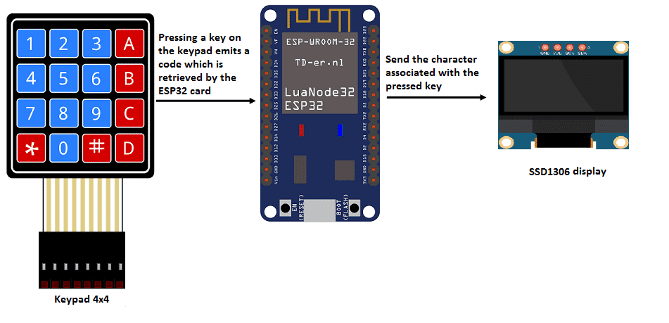
In this tutorial we will see how to manipulate the 4×4 matrix keypad by the ESP32 card. If a key on the 4×4 matrix keyboard is pressed, the associated character is displayed in the SSD1306 display.
4×4 Matrix keypad operation with ESP32 board:
Necessary components
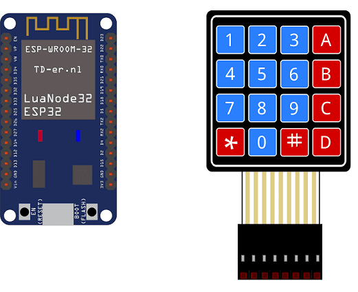
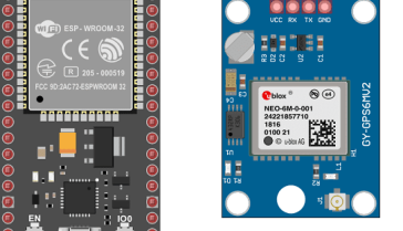
ESP32 Card
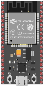
An ESP32 card is a development board or module that is based on the ESP32 microcontroller developed by Espressif. It typically includes the ESP32 chip, as well as a number of peripheral components, such as RAM, flash memory, power management, and input/output (I/O) pins. ESP32 cards can come in a variety of form factors, including the ESP32-DevKitC, ESP32-WROVER, ESP32-PICO-D4 and more.
ESP32 card can be programmed using various programming languages such as C, C++, Python and MicroPython. The ESP32 has a built-in support for the Arduino IDE which makes it easy to program and debug.
4×4 keypad
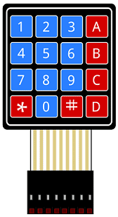
A 4×4 keypad is a type of input device that consists of a grid of 4 rows and 4 columns of buttons. It is often used as a simple, low-cost way to add numerical input to a project, such as an access control system or calculator.
The buttons on the keypad are typically labeled with the digits 0-9, as well as a few additional characters such as * and #. Each button is connected to a pin on the keypad’s circuit board, and the pins are connected to a microcontroller or other electronic device.
connecting wires

Wires are used to transmit electrical signals and power to various components such as motors, sensors, and microcontrollers. It’s important to properly route and secure the wires to prevent tangles and damage. There are several methods for doing this, including using cable ties, clamps, and wire looms. It’s also a good idea to use different colors or labeling to identify the different wires and their functions. When connecting wires in a robot, it’s important to follow proper safety procedures, such as using the correct wire stripper and connectors, and wearing protective equipment such as gloves and safety glasses.
test plate

A test plate is a type of device used in robotics to test the functionality and performance of various components or systems. It is typically a physical platform or structure that is designed to hold and support various test items or devices, such as sensors, actuators, motors, or other types of mechanical or electrical components. Test plates can be used to simulate different environments or conditions, such as temperature, humidity, vibration, or other factors, in order to evaluate the performance of the components or systems being tested. They can also be used to perform a variety of diagnostic or diagnostic tests, such as stress testing, endurance testing, or other types of evaluations.
Assembly
We connect the 8 outputs of the keypad to the 8 pins of the ESP32 card following this order: D2, D4, D5, D18, D19, D16, D15 and D23.
For the SSD1306 display we connect:
-
the SDA pin to the D21 pin of the ESP32 board
-
the SCL pin to the D22 pin of the ESP32 board
-
the GND pin to the GND pin of the ESP32 board
-
the VCC pin to the 5V pin of the ESP32 board

Micropython program:
Here is the micropython program that allows you to enter characters from the 4×4 matrix keyboard and display it on the SSD1306 display.
Note: the following library must be imported: ssd1306
|
1 2 3 4 5 6 7 8 9 10 11 12 13 14 15 16 17 18 19 20 21 22 23 24 25 26 27 28 29 30 31 32 33 34 35 36 37 38 39 40 41 42 43 44 45 46 47 48 49 50 51 52 53 54 55 56 57 58 59 60 61 62 63 64 65 |
from machine import Pin,I2C import ssd1306 from time import sleep import utime import machine WIDTH = 128 HEIGHT = 64 i2c = I2C(scl=Pin(22), sda=Pin(21)) #Init i2c oled=ssd1306.SSD1306_I2C(128,64,i2c,0x3c) # CONSTANTS KEY_UP = const(0) KEY_DOWN = const(1) keys = [['1', '2', '3', 'A'], ['4', '5', '6', 'B'], ['7', '8', '9', 'C'], ['*', '0', '#', 'D']] # Pin names for Pico cols = [19,16,15,23] rows = [2,4,5,18] # set pins for rows as outputs row_pins = [Pin(pin_name, mode=Pin.OUT) for pin_name in rows] # set pins for cols as inputs col_pins = [Pin(pin_name, mode=Pin.IN, pull=Pin.PULL_DOWN) for pin_name in cols] def init(): for row in range(0,4): for col in range(0,4): row_pins[row].value(0) def scan(row, col): """ scan the keypad """ # set the current column to high row_pins[row].value(1) key = None # check for keypressed events if col_pins[col].value() == KEY_DOWN: key = KEY_DOWN if col_pins[col].value() == KEY_UP: key = KEY_UP row_pins[row].value(0) # return the key state return key print("starting") # set all the columns to low init() while True: oled.fill(0) for row in range(4): for col in range(4): key = scan(row, col) if key == KEY_DOWN: oled.text("Key Pressed: ",10,0) print("Key Pressed", keys[row][col]) oled.text(keys[row][col], 55, 30) # display the character associated with the key press oled.show() last_key_press = keys[row][col] |
You can also see

0 commentaire
Leave a comment


Recent tutorials


Most viewed tutorials


Most commented tutorials


Scroll to Top