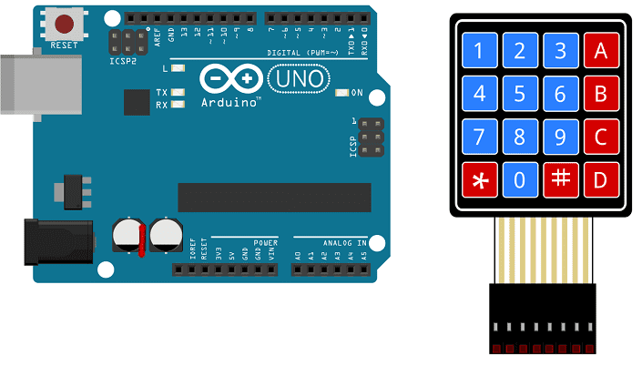
Arduino I2C LCD 1602 Display Keypad 4x4
Using the 4×4 Matrix Keypad with Arduino
The Arduino microcontroller can be easily interfaced with a 4×4 matrix keypad using a variety of methods, including digital input and matrix scanning.
One method to interface a 4×4 matrix keypad with an Arduino is to use digital input. This method involves connecting the rows of the keypad to digital pins on the Arduino, and connecting the columns of the keypad to digital pins on the Arduino. The program then reads the state of the rows and columns of the keypad to determine which key was pressed. You will also need to create a keymap which will map the button press to its corresponding character or number.
Another method is Matrix scanning , in this method You will connect all the row pins of the keypad to the arduino digital pins and all the column pins of the keypad to the arduino digital pins. And then in the arduino code you will write a loop where you will check each button press by sending a low signal to a row pin and then reading all the column pin one by one. If any of the column pins read high then it means the button of that column and row is pressed.
Both methods require a bit of programming and you need to include the keypad library in the arduino sketch. In both methods, once a key is pressed, the program can take an action such as displaying the pressed key on a serial monitor or sending a command to another device.
Keep in mind that different libraries and different hardware will affect how you will connect the 4×4 matrix keypad to the arduino and how the code will look like.
Purpose of this tutorial:
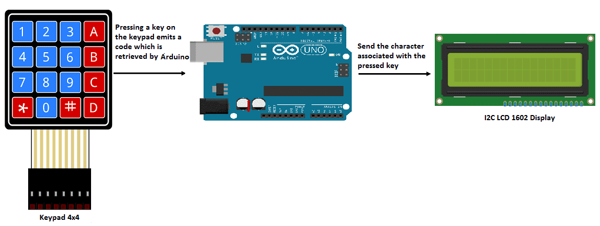
In this tutorial we will see how to manipulate the 4×4 matrix keypad with the Arduino board. If a key on the 4×4 matrix keypad is pressed, the associated character is displayed in the LCD display.
4×4 Matrix keypad operation with Arduino:
Necessary components
Arduino UNO
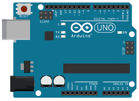
The Arduino UNO is a microcontroller board based on the ATmega328 microcontroller. It is one of the most popular boards in the Arduino family and is commonly used for a wide range of projects, including controlling motors, monitoring sensors, and communicating with other devices.
The Arduino UNO has a number of features that make it well-suited for a wide range of projects:
- Input/output pins: The Arduino UNO has 14 digital input/output pins (of which 6 can be used as PWM outputs), 6 analog inputs, a 16 MHz quartz crystal, a USB connection, a power jack, an ICSP header, and a reset button.
- Memory: The ATmega328 microcontroller on the Arduino UNO has 32 KB of flash memory for storing programs (of which 0.5 KB is used by the bootloader), 2 KB of SRAM, and 1 KB of EEPROM.
- Power: The Arduino UNO can be powered via the USB connection or an external power supply. The board can operate on an external supply of 6 to 20 volts.
- Compatibility: The Arduino UNO is compatible with a wide range of shields (add-on boards) and libraries, making it easy to expand its capabilities for various projects.
- Community: The Arduino UNO has an active community of users who share their knowledge and experiences, providing a wealth of information and resources for those who want to learn more about the board.
It’s easy to program using the Arduino IDE(Integrated Development Environment) which is a simple and easy-to-use software that can be downloaded for free. You can use this software to write, upload and debug code on the Arduino UNO. It’s compatible with many programming languages such as C, C++ and also it support many library functions to easily interface with different sensors, actuators and other devices.
4×4 matrix keypad
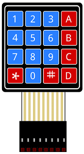
A 4×4 matrix keypad is a type of input device that consists of 16 buttons arranged in a 4×4 grid. These buttons can be used to input numerical or alphanumeric data, and are commonly used in applications such as access control systems, security systems, and point-of-sale terminals. The 4×4 matrix keypad is typically composed of 16 individual switch buttons, arranged in a 4×4 grid. Each button is connected to a row and a column. Pressing a button causes a connection to be made between the row and column to which the button is connected.
There are different ways to connect a 4×4 matrix keypad to a microcontroller like using digital input, or matrix scanning but both methods require some programming and additional components like resistors to protect the microcontroller from high voltage.
When using a 4×4 matrix keypad with a microcontroller, it’s important to consider the pinout and layout of the keypad. Some keypads have the rows and columns labeled, while others may not. In addition, different keypads may have different pinout arrangements, so it is important to consult the datasheet for the specific keypad you are using.
In order to use the keypad, you’ll need to create a keymap that defines the mapping of the keys to their corresponding characters, numbers or codes. Some keypad library already provide a pre-defined keymap of a 4×4 matrix keypad.
I2C LCD 1602 display
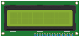
An I2C LCD 1602 display is a type of liquid crystal display (LCD) that uses the I2C protocol for communication with a microcontroller. The “1602” part of the name refers to the number of characters that can be displayed on the screen, which is 16 characters per line and 2 lines.
The I2C LCD 1602 display typically has a small circuit board with the LCD screen and an I2C backpack module attached to it. The backpack module allows the LCD to communicate with the microcontroller using the I2C protocol, which uses only two wires (SDA and SCL) for communication.
To use an I2C LCD 1602 display with an Arduino, you will need to install a library that provides the functions required to communicate with the display. There are several libraries available for this purpose, such as the LiquidCrystal_I2C library.
In order to use the I2C LCD 1602 with an Arduino, you will also need to connect the display to the Arduino board. The pinout of the I2C LCD 1602 display typically includes VCC, GND, SDA, and SCL. Connect the VCC pin to the 5V pin on the Arduino, the GND pin to the GND pin on the Arduino, the SDA pin to the SDA pin on the Arduino, and the SCL pin to the SCL pin on the Arduino.
Once you have connected the display and installed the library, you can use the provided functions to initialize the display, write text to it, clear it and change cursor position.
It’s important to note that the library you are using and the I2C LCD 1602 display you are using may have different pinout arrangements and different initialization instructions, so it is important to consult the datasheet and the documentation of the library you are using to ensure that you have the correct connections and initialization instructions for your specific display.
connecting wires

Wires are used to transmit electrical signals and power to various components such as motors, sensors, and microcontrollers. It’s important to properly route and secure the wires to prevent tangles and damage. There are several methods for doing this, including using cable ties, clamps, and wire looms. It’s also a good idea to use different colors or labeling to identify the different wires and their functions. When connecting wires in a robot, it’s important to follow proper safety procedures, such as using the correct wire stripper and connectors, and wearing protective equipment such as gloves and safety glasses.
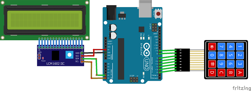
Assembly
We connect the 8 outputs of the keypad to the 8 pins of the Arduino (from 2 to 9).
For the I2C LCD 1602 display we connect:
-
the SDA pin to the A4 pin of the Arduino
-
the SCL pin to the A5 pin of the Arduino
-
the GND pin to the GND pin of the Arduino
-
the VCC pin to the 5V pin of the Arduino
Arduino program
Here is the Arduino program that can input characters from the 4×4 matrix keyboard and display it on the LCD display.
|
1 2 3 4 5 6 7 8 9 10 11 12 13 14 15 16 17 18 19 20 21 22 23 24 25 26 27 28 29 30 31 |
#include <LiquidCrystal_I2C.h> #include <Keypad.h> const int ROW_NUM = 4; //four rows const int COLUMN_NUM = 4; //four columns LiquidCrystal_I2C lcd(0x27, 20, 4); char keys[ROW_NUM][COLUMN_NUM] = { {'1','2','3', 'A'}, {'4','5','6', 'B'}, {'7','8','9', 'C'}, {'*','0','#', 'D'} }; byte pin_rows[ROW_NUM] = {9, 8, 7, 6}; //connect to the row pinouts of the keypad byte pin_column[COLUMN_NUM] = {5, 4, 3, 2}; //connect to the column pinouts of the keypad Keypad keypad = Keypad( makeKeymap(keys), pin_rows, pin_column, ROW_NUM, COLUMN_NUM ); void setup(){ lcd.init(); // display initialization lcd.clear(); lcd.backlight(); // activate the backlight lcd.setCursor(0, 0); // stand in the front line } void loop(){ char key = keypad.getKey(); if(key) //press a key on the 4x4 matrix keypad { lcd.print(key); // Display the entered character on the LCD display delay(100); } } |
You can also see

0 commentaire
Leave a comment


Recent tutorials


Most viewed tutorials


Most commented tutorials


Scroll to Top