ESP32 LED Project SSD1306 display
Traffic light with SSD1306 display controlled by ESP32
A traffic light is an electronic device that controls the flow of vehicular and pedestrian traffic using a set of colored lights. The most common traffic light consists of three lights: red, yellow, and green. The red light indicates that vehicles and pedestrians should stop, the yellow light indicates that the red light is about to turn on and the green light indicates that vehicles and pedestrians can proceed.
Traffic lights are typically controlled by a central controller that receives input from sensors, such as traffic cameras, loop detectors, and push buttons, to determine when to change the light. The controller then sends signals to the traffic lights to change the color of the lights.
Traffic lights are widely used in roads, highways, and intersections to regulate the flow of traffic, reduce congestion, and prevent accidents. They are often used in conjunction with other traffic control devices such as signs, signals, and road markings.
Traffic lights can also be used in other types of applications, such as signaling for industrial processes, and to indicate the status of a machine or equipment.
Traffic lights can be controlled by microcontrollers such as ESP32, by using sensors and program logic to control the lights, this is commonly used in DIY projects and educational projects. It’s worth noting that building a fully functional traffic light that can be used on the road is a complex task and it’s important to comply with the regulations and safety standards for traffic lights.
Objective of this project:
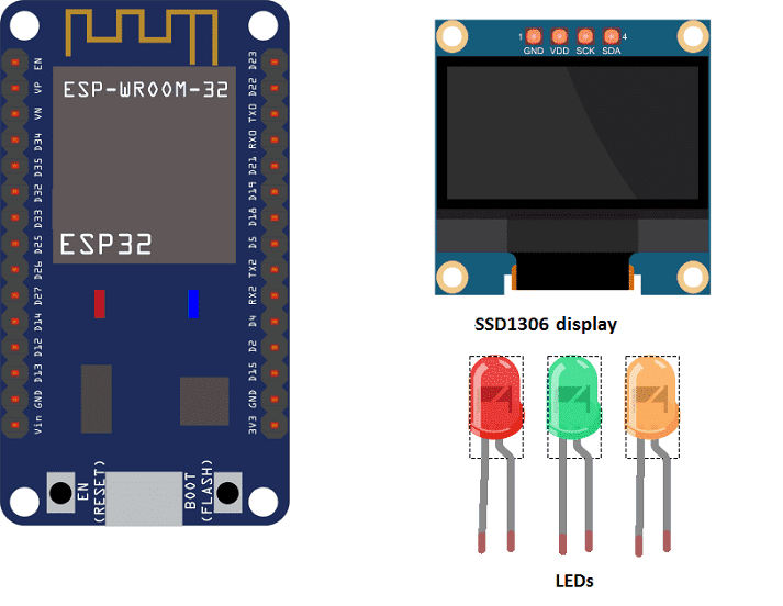
The objective of this project is to create a traffic light following these steps:
- The red LED lights up for 3 seconds, displaying “Stop” on the SSD1306 display.
- After 3 seconds the red LED goes out and another green LED lights up, also for 3 seconds, displaying “Cross”
- Once the green LED is off, a third, orange LED lights up for 2 seconds, displaying “Cross quickly”.
- Then the program resumes in a loop.
Necessary components
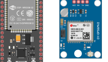
ESP32
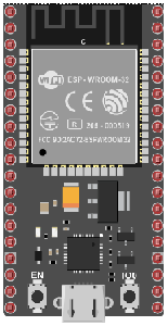
The ESP32 is a low-cost, low-power microcontroller with built-in Wi-Fi and Bluetooth capabilities. It is a popular choice for IoT projects and is commonly used for a variety of applications such as home automation, wireless control, and sensor data logging. The ESP32 features a dual-core processor, a rich set of peripherals, and support for a wide range of protocols. It can be programmed using the Arduino IDE and various other programming languages such as C, C++, and MicroPython.
Additionally, the ESP32 has a wide range of features including:
- A high-performance processor with a clock speed of up to 240 MHz
- Support for various types of wireless connectivity such as Wi-Fi, Bluetooth, and Bluetooth Low Energy (BLE)
- Multiple communication interfaces such as I2C, SPI, UART, and I2S
- A large number of GPIO pins to connect to external devices and sensors
- A built-in security module for secure communication
The ESP32 is often used in projects where a low-cost, low-power device with Wi-Fi and Bluetooth capabilities is needed, and it is commonly used with other sensors and devices to build IoT projects, home automation systems, wireless control systems, and data logging systems.
SSD1306 display
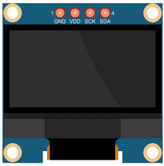
The SSD1306 is a monochrome OLED (Organic Light Emitting Diode) display that can be used to display text and graphics. It is a small, low-power display that can be easily integrated into a wide variety of projects.
The SSD1306 display is controlled using an I2C or SPI interface, which allows it to communicate with a microcontroller or microprocessor. It typically requires only a few connections to the microcontroller, such as Vcc, GND, SDA and SCL for I2C or SCK, MOSI, CS, DC and RST for SPI.
The SSD1306 display has a resolution of 128×64 pixels, and it can display text and graphics using a monochrome pixel format. The display has an integrated charge pump that allows it to operate at a voltage as low as 2.7V. This allows for low power consumption and makes it suitable for battery-powered projects.
The SSD1306 display can be controlled using a variety of libraries that are available for different platforms such as Arduino, Raspberry Pi, ESP32, etc. These libraries provide a set of functions for controlling the display and make it easy to use the SSD1306 display in your projects.
The libraries typically provide functions for initializing the display, clearing the display, setting the cursor position, and writing text or graphics to the display. They also provide functions for controlling the display’s contrast and brightness.
Overall, the SSD1306 display is a versatile and low-power display that can be easily integrated into a wide variety of projects. It is a popular choice for creating small, portable, and battery-powered devices such as digital clocks, temperature displays, and other small graphic displays.
Red LED- Yellow LED – Green LED
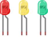
An LED (Light Emitting Diode) is a semiconductor device that emits light when an electric current is passed through it. LEDs are widely used in a variety of applications because they are energy-efficient, have a long lifespan, and are available in a wide range of colors.
LEDs can be found in many electronic devices such as televisions, smartphones, computers, and traffic lights. They are also used in automotive lighting, general illumination, and as indicator lights.
Connecting wires

Connecting wires refers to the process of physically connecting wires or cables to a device or circuit in order to establish an electrical connection. This can be done by using various connectors such as plugs, sockets, or terminal blocks. The wires are typically color-coded to indicate their function, such as red for power, black for ground, and yellow for signals.
Test plate

A test plate is a type of circuit board that is used to test electronic components. It typically consists of a flat board made of a non-conductive material, such as plastic or fiberglass, with a number of holes or pads that are used to connect electronic components. The test plate allows you to connect electronic components and test them easily.
Mounting
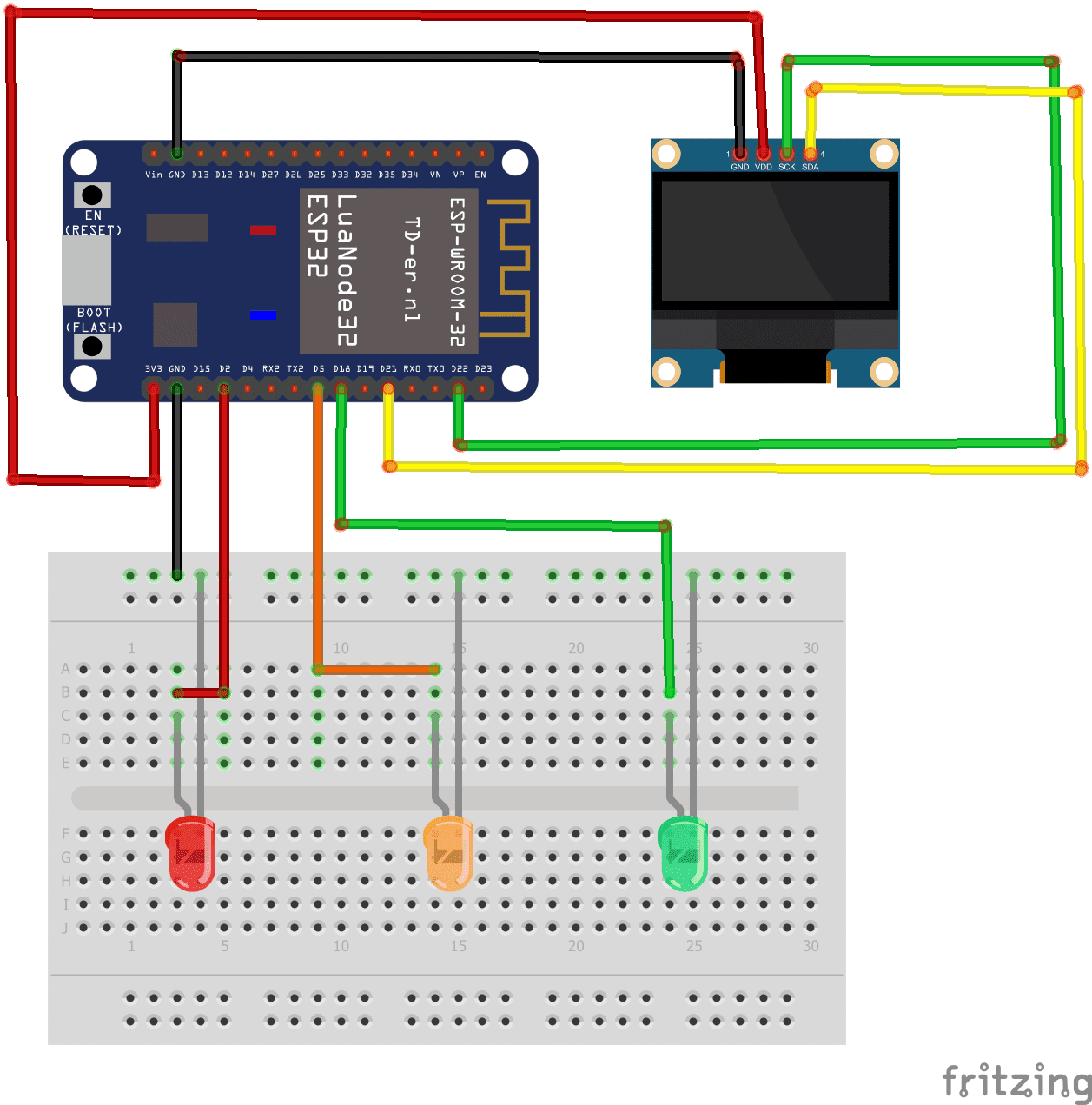
To carry out the assembly, you can connect:
LEDs :
-
the terminal (+) of green LED to pin D18 of the ESP32 board
-
the yellow LED (+) terminal to pin D5 of the ESP32 board
-
the red LED (+) terminal to pin D2 of the ESP32 board
-
the terminal (-) of each LED has GND of the ESP32 board
SSD1306 display:
-
the SCL pin to pin D22 of the ESP32 board
-
the SDA pin to the D21 pin of the ESP32 board
-
the VCC pin to the 3.3V pin of ESP32 board
-
the GND to GND pin of the ESP32 board
Micropython program
|
1 2 3 4 5 6 7 8 9 10 11 12 13 14 15 16 17 18 19 20 21 22 23 24 25 26 27 28 29 30 31 32 33 34 35 36 37 |
from machine import Pin, I2C import ssd1306 from time import sleep # ESP32 Pin assignment i2c = I2C(-1, scl=Pin(22), sda=Pin(21)) oled_width = 128 oled_height = 64 oled = ssd1306.SSD1306_I2C(oled_width, oled_height, i2c) led_jaune=Pin(5,Pin.OUT) led_rouge=Pin(2,Pin.OUT) led_verte=Pin(18,Pin.OUT) while True: led_jaune.value(1) #Turn on yellow LED led_rouge.value(0) led_verte.value(0) oled.text('Cross fast', 0, 10) oled.show() time.sleep(1) # wait 1s oled.fill(0) #clear the screen led_jaune.value(0) led_rouge.value(1) # Turn on red LED led_verte.value(0) oled.text('stop', 0, 10) oled.show() time.sleep(3) # wait 3s oled.fill(0) led_jaune.value(0) led_rouge.value(0) led_verte.value(1) # Turn on green LED oled.text('Cross', 0, 10) oled.show() time.sleep(3) # wait 3s oled.fill(0) |
Note: the following library must be imported: ssd1306
You can also see

0 commentaire
Leave a comment


Recent tutorials


Most viewed tutorials


Most commented tutorials


Scroll to Top