Arduino I2C LCD 1602 Display LED Project
Traffic light with LCD display controlled by Arduino
Presentation of traffic light
A traffic light is a signaling device at road intersections, pedestrian crossings, and other locations to indicate when it is safe to drive, walk, or cycle. They are typically composed of three lights: red, yellow (or amber), and green. The red light indicates that vehicles or pedestrians should stop, the yellow light warns that the red signal is about to appear, and the green light indicates that it is safe to proceed. Traffic lights are used to control the flow of traffic and reduce collisions between vehicles, pedestrians, and bicycles. Some traffic lights also include additional features such as a walk signal for pedestrians and a left-turn signal for vehicles.
A traffic light with an LCD display controlled by an Arduino is a system that utilizes an Arduino microcontroller to control the operation of a traffic light and an LCD display to show the current status of the traffic light.
The system works by connecting the traffic light lights (red, yellow, green) to the Arduino‘s digital output pins and using the Arduino‘s programming capabilities to control when each light is on or off. The LCD display is connected to the Arduino‘s digital input/output pins, and the Arduino‘s programming is used to display the current status of the traffic light on the LCD screen.
This system can be used in various applications such as in educational projects, simulating traffic lights in parking lots or small streets, or in traffic management systems. The Arduino can be programmed to change the traffic light pattern based on the traffic flow, time of day, or other factors. The LCD display can be used to display various information such as the current time, the duration of each traffic light phase, and the current traffic flow.
It would be a DIY project, it’s not commonly used in real-world traffic management systems.
Objective of this project:
The objective of this project is to realize a traffic light following these steps:
– The red led lights for 3 seconds by displaying on the LCD display «Stop».
– After 3 seconds the red led goes out and lights another green, also for 3 seconds, displaying “Cross”
– Once the green led goes out , lights a third, orange, for 2 seconds by displaying “Cross fast”.
Then the program resumes in loop .
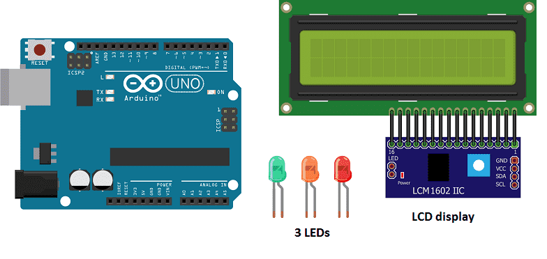
Necessary components
Arduino UNO
The Arduino UNO is a microcontroller board based on the ATmega328P. It has 14 digital input/output pins, 6 analog inputs, a 16 MHz quartz crystal, a USB connection, a power jack, an ICSP header, and a reset button. It is the most popular and widely used board among the Arduino boards.
The Arduino UNO can be programmed using the Arduino programming language, which is based on C++. It uses a simple and intuitive programming environment, making it easy for beginners to get started with microcontroller programming.
The Arduino UNO can be connected to various sensors and actuators to control different devices and perform different tasks. For example, it can be used to control motors, read data from sensors, display information on an LCD screen, and communicate with other devices via serial communication protocols such as I2C and SPI.
The Arduino UNO can also be powered by a USB cable or an external power supply, making it easy to use in a wide range of projects and applications. It’s compatible with a wide range of shields (expansion boards) that adds functionality to the board, such as Ethernet, WiFi, and Bluetooth, and it’s widely supported by a strong and active community, which provides a lot of tutorials, examples and libraries to help users to get the most of the board.
Red LED- Yellow LED – Green LED
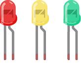
An LED (Light Emitting Diode) is a semiconductor device that emits light when an electric current is passed through it. LEDs are widely used in a variety of applications because they are energy-efficient, have a long lifespan, and are available in a wide range of colors.
LEDs can be found in many electronic devices such as televisions, smartphones, computers, and traffic lights. They are also used in automotive lighting, general illumination, and as indicator lights.
3 220 ohm resistors
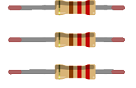
Resistors are passive electronic components that are used to control the flow of electric current in a circuit. They are typically made of a conductive material, such as carbon or metal, that resists the flow of electricity. The resistance of a resistor is measured in ohms (Ω). Resistors can be used to divide voltage, limit current, and bias active devices. They are widely used in electronic circuits for a wide range of applications.
LCD I2C 160A display
An LCD I2C 160A display is a type of liquid crystal display (LCD) that uses the I2C communication protocol and has a screen size of 160×128 pixels. The I2C (Inter-Integrated Circuit) protocol is a communication protocol that allows multiple devices to communicate with each other over a shared bus. This means that the LCD display can be connected to a microcontroller, such as an Arduino, using just two wires for communication and power.
The I2C interface allows for a simpler wiring and board design, and also multiple LCD can be connected to a single microcontroller by just changing the I2C address of each display. The size of 160×128 pixels provides a decent resolution for displaying text, images or graphics.
This type of LCD display can be used in various projects such as in home automation, weather station, data logger, etc. It’s also compatible with many development board like Raspberry Pi, Arduino, etc.
connecting wires

Connecting wires are used to connect various components in an electronic circuit. They allow for the transfer of electricity, data, or signals between different devices and components.
When connecting wires to an Arduino or other microcontroller, it is important to pay attention to the correct pinout. The pinout refers to the arrangement of pins on the microcontroller and the corresponding function of each pin. The Arduino pinout can be found in the documentation provided by the manufacturer, or in various resources available online.
test plate

A test plate, also known as a test jig, is a device used to test electronic circuits and components. It is a board or plate that has been designed to hold and connect various components and devices in a specific configuration, allowing for the easy testing and measurement of their performance.
A test plate can be used to test various types of electronic circuits and components, such as microcontrollers, sensors, and actuators. It typically includes connectors and sockets for connecting wires, power supply and measurement devices such as multimeters, oscilloscopes, and power supplies.
Mounting
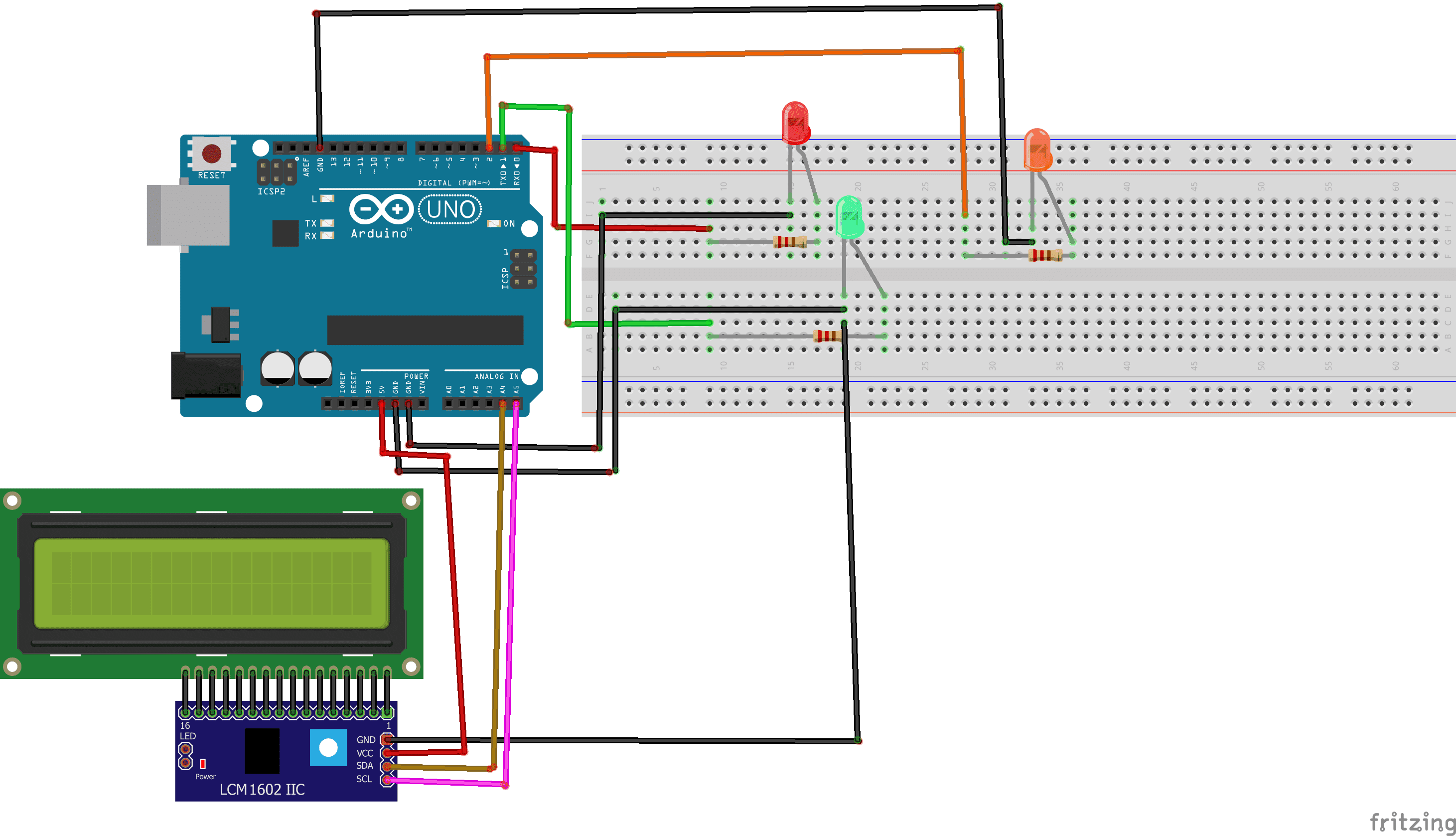
To make the assembly we can connect:
LEDs :
- the green LED resistance to the Arduino PIN 0
- the yellow LED resistance to the Arduino PIN 1
- the red LED resistance to the Arduino PIN 2
For LCD display :
- SCL pin of the LCD display to A5 pin of the Arduino
- SDA pin of the LCD display to A4 pin of the Arduino
- VCC pin of the LCD display to 5v pin of the Arduino.
- GND LCD display to GND pin of the Arduino
Program
|
1 2 3 4 5 6 7 8 9 10 11 12 13 14 15 16 17 18 19 20 21 22 23 24 25 26 27 28 29 30 31 32 33 34 35 36 37 38 39 40 |
#include <LiquidCrystal_I2C.h> LiquidCrystal_I2C lcd(0x27, 20, 4); void setup(){ lcd.init(); pinMode(0,OUTPUT); //sets the number 0 digital pin of the Arduino in output mode pinMode(1,OUTPUT); //sets the number 1 digital pin of the Arduino in output mode pinMode(2,OUTPUT); //sets the number 2 digital pin of the Arduino in output mode } void loop(){ lcd.backlight(); lcd.clear(); digitalWrite(0,HIGH); //red LED lights up digitalWrite(1,LOW); // green LED goes out digitalWrite(2,LOW); //orange LED goes out lcd.setCursor(0, 0); lcd.print("STOP"); delay(3000); lcd.clear(); digitalWrite(0,LOW); //red LED goes out digitalWrite(1,HIGH); //green LED lights up digitalWrite(2,LOW); // orange LED goes out lcd.print("Cross"); delay(3000); lcd.clear(); digitalWrite(0,LOW); //red LED goes out digitalWrite(1,LOW); // green LED goes out digitalWrite(2,HIGH); //orange LED lights up lcd.print("Cross fast"); delay(1000); } |
You can also see

3 commentaires
Leave a comment


Recent tutorials


Most viewed tutorials


Most commented tutorials


Scroll to Top
2022 30-11-2222
Thanks for finally writing about > Traffic light with LCD display controlled by Arduino 2022
tracfone special coupon 2022 27-11-2222
Hey there, You've done an incredible job. I'll certainly digg it and personally suggest to my friends. I'm confident they will be benefited from this site.
Travis 13-07-2222
Spot on with this write-up, I truly believe that this website needs much more attention. I'll probably be returning to read more, thanks for the info!