Railway barriers are physical barriers that are used to prevent vehicles or pedestrians from crossing a railway track at an undesignated location. These barriers are typically made of steel or concrete, and are used to block access to the track while trains are passing through. The barriers can be raised or lowered depending on the state of the track, and are typically controlled by a signal system that receives information from trains about their location and speed. The barriers can be operated either manually or automatically, and are typically used in areas where there is a high risk of accidents, such as in urban areas or near level crossings. They also can be used to protect wildlife or people crossing the tracks in rural areas.
Objective of project
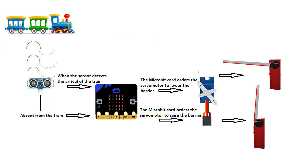
Simulating the functioning of railway barriers with Microbit is a project that involves using a Microbit microcontroller to control the movement of a model railway barrier. The Microbit is a low-cost, low-power microcontroller board that has built-in WiFi and Bluetooth capabilities. It has a powerful processing capability, and can be programmed using the Makecode.
In this project, the Microbit can be connected to a motor that controls the movement of the barrier, and programmed to raise and lower the barrier based on input from sensors or other devices. For example, you can use infrared sensors or ultrasonic sensors to detect the approaching of a train, and use this information to trigger the barrier to lower. Alternatively, you can use a push button or other input device to manually control the barrier’s movement. The Microbit can also be programmed to communicate with other devices wirelessly, such as a remote control, a smartphone, or a computer, to control the barrier, or to receive status updates from the barrier.
In this project we will realize a system that simulate the operation of automatic barriers for railways trains.
We will design this system using:
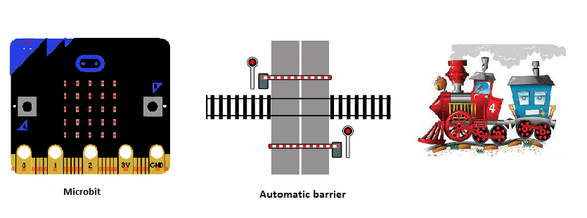
- Micro:bit card
-
two ultrasonic sensors hc-sr04 for the detection of the arrival of the train.
-
two servomotors to lower or raise the barriers
Operation of the barrier controlled by Microbit:
Components required
Micro:bit card
HC-SR04 ultrasonic sensor
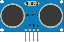
The HC-SR04 ultrasonic sensor is a low-cost and widely used sensor that can be used to detect the approaching of a train in a railway barrier system. This sensor uses an ultrasonic transducer to emit a sound wave and measure the time it takes for the wave to bounce back after hitting an object.
The HC-SR04 has four pins: VCC, Trig, Echo, and GND. The VCC pin is connected to the power supply, typically 5V for Microbit. The Trig pin is used to trigger the sensor to emit a sound wave, and the Echo pin is used to receive the reflected wave. The GND pin is connected to ground.
In a railway barrier system, the HC-SR04 ultrasonic sensor can be placed along the track to detect the approaching of a train. The sensor emits a sound wave by sending a signal to the Trig pin, and waits for the Echo pin to receive the reflected wave. By measuring the time delay between the signal and the echo, the sensor can calculate the distance to the train. When the train is detected within a certain range, the sensor sends a signal to the barrier control system which then triggers the barrier to lower.
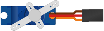
A servo motor can be used to control the movement of a railway barrier by providing precise control over the position of the barrier. A servo motor is a type of actuator that uses a closed-loop control system to control the position of a shaft or other mechanical component.
A typical servo motor consists of a DC motor, a gear train, a position sensor (such as a potentiometer), and control electronics. The control electronics use the position feedback from the sensor to adjust the motor’s power and direction in order to move the shaft to the desired position.
In a railway barrier system, the servo motor can be connected to the barrier and controlled by the barrier control system to raise and lower the barrier. The control system can be programmed to move the servo to specific positions, corresponding to the barrier being fully raised or fully lowered. The servo can also be programmed to move the barrier to intermediate positions, for example, to partially lower the barrier for a slow-moving train.
The use of a motor servo in the railway barrier system allows for precise control of the barrier’s position, and also provides the ability to make fine adjustments to the barrier’s position in case of any errors. It’s important to choose a servo motor that has the appropriate torque and power rating to move the barrier smoothly and efficiently.
Supply power module
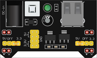
A supply power module is a device that is used to provide a stable and regulated power supply to a circuit or system. In the context of a Microbit based railway barrier system, a 5V/3.3V supply power module can be used to provide a stable voltage to the microcontroller and the other electronic components of the system, such as the ultrasonic sensors, servo motor, and control electronics.
LEDs
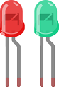
LEDs (light-emitting diodes) can be used in a railway barrier system to indicate the state of the barrier and provide visual cues to the users. LEDs can be used to indicate when the barrier is in the raised or lowered position, when a train is approaching, or when a fault or error has occurred.
For example, a green LED can be used to indicate that the barrier is in the raised position, and a red LED can be used to indicate that the barrier is in the lowered position.
The LEDs can be connected to the control system, and their state can be controlled using the Microbit microcontroller. The LEDs can be connected to digital output pins of the Microbit board, and the state of the LED can be controlled by writing a digital signal to the corresponding pin.
The use of LEDs in the railway barrier system can help to improve the usability and safety of the system by providing clear and visible cues to the users about the state of the barrier and any potential hazards. It’s important to choose LEDs that are visible under different lighting conditions, and that are durable and reliable.
test plate

A test plate is a device that is used to perform tests or experiments on a circuit or system. In the context of an Microbit based railway barrier system, a test plate can be used to test and debug the system before it is deployed in a real-world setting.
A test plate typically includes a set of input and output connectors, such as push buttons, LEDs, and sensors, that can be used to simulate real-world inputs and observe the system’s response. It can also include power supply connectors and a power switch to enable the test plate to be powered on and off.
The test plate can be used to test the functionality of the system and its components, such as the microcontroller, the ultrasonic sensors, the servo motor, and the control electronics. For example, you can use the test plate to simulate a train approaching and observe the system’s response by lowering the barrier and turning on the yellow LED. You can also use the test plate to test the system’s reaction to different inputs or scenarios, such as manual operation, or a fault in the system.
connecting wires

Connecting wires are used to connect the various components of a circuit or system together. In the context of an Microbit based railway barrier system, connecting wires are used to connect the microcontroller, sensors, actuators, LEDs and other devices to the control system and the power supply.
Connecting wires can be made of copper or other conductive materials and are typically coated with a plastic or rubber insulation to protect against electrical short circuits. They come in different sizes, lengths and colors, and often have a connector on each end to connect the wires to the components.
There are different types of connecting wires such as jumpers, DuPont wires, ribbon cable, etc. Jumpers are short wires that have connectors on both ends and are used to connect two points on a circuit board. DuPont wires are single wires with connectors on each end, they are commonly used to connect sensors and actuators to the control board. Ribbon cables are multi-conductor cables that are used to connect multiple devices to the control board.
Connecting wires play a critical role in the functioning of the railway barrier system, as they are responsible for transmitting the electrical signals and power between the various components of the system. It’s important to use the appropriate type of wire for the specific application and to ensure that the connections are secure and free of any damage to avoid any malfunction or system failure.
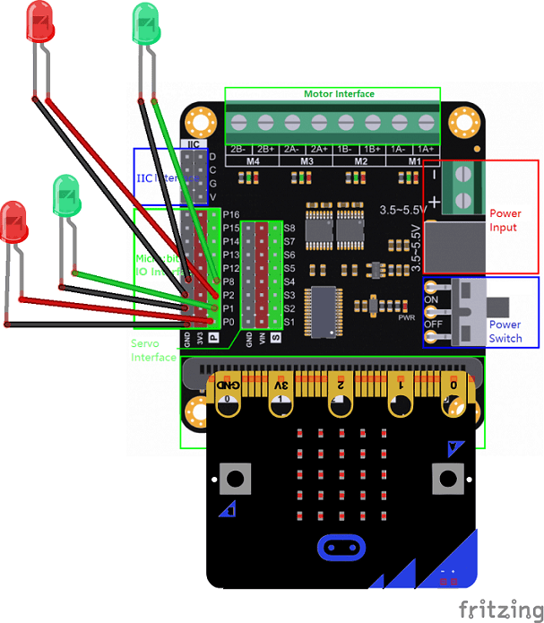
Assembly:
To do the assembly, we connected:
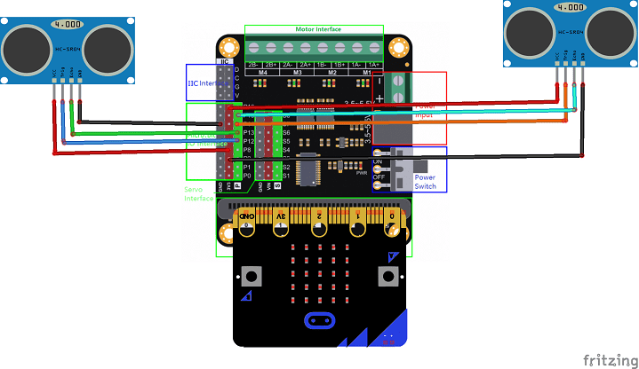
For the first sound sensor HC-SR04:
-
the VCC pin to the 3.3V pin of the Micro:bit
-
the Trig pin to the P12 pin of the Micro:bit
-
the ECHO pin to pin P13 of the Micro:bit
-
the GND pin to the GND pin of the Micro:bit
For the second sound sensor HC-SR04:
-
the VCC pin to the 3.3V pin of the Micro:bit
-
the Trig pin to pin P14 of the Micro:bit
-
the ECHO pin to the P15 pin of the Micro:bit
-
the GND pin to the GND pin of the Micro:bit
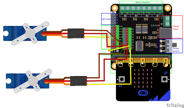
For the first servomotor:
-
red wire: power supply wire to be connected to the 5V terminal of the GPIO card
-
brown wire: wire to connect to the GND pin of the Micro:bit
-
Yellow: Positioning signal wire connected to Micro: bit pin S1
For the second servomotor:
-
red wire: power supply wire to be connected to the 5V terminal of the GPIO card
-
brown wire: wire to connect to the GND pin of the Micro:bit
-
Yellow: Positioning signal wire connected to Micro:bit pin S2
For LEDs:
-
the terminals (-) of the LEDs to GND of the Microbit
-
the (+) terminal of the first red LED at P0 of Microbit
-
the (+) terminal of the first green LED at P1 of Microbit
-
the (+) terminal of the first red LED to P2 of Microbit
-
the (+) terminal of the first green LED at P8 of Microbit
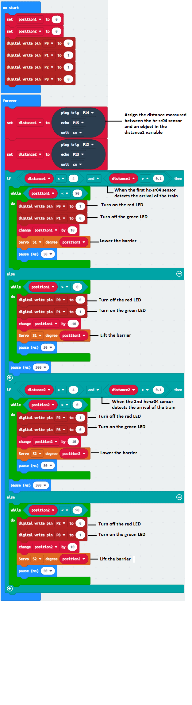
Makecode Program
Here is the makecode program which allows you to:
-
calculate the distance between the HC-SR04 sensor and the detected object
-
raise or lower barriers
-
turn LEDs on or off
You can also see

0 commentaire
Leave a comment


Recent tutorials


Most viewed tutorials


Most commented tutorials


Scroll to Top