Keypad 4x4 Micro:bit Microbit Driver Expansion Board Project
Door security system controlled by Micro:bit
A door security system is a system that is used to protect a door and the area around it from unauthorized access. There are many different types of door security systems, ranging from simple locks to complex, networked systems that use sensors, cameras, and other types of technology.
Some common features of door security systems include:
- Locks: Locks are the most basic and common form of door security. They can be mechanical or electronic, and they can range from simple deadbolts to more complex locking systems.
- Alarms: Alarms can be triggered if someone tries to tamper with the lock or open the door without authorization.
- Cameras: Cameras can be used to monitor the area around the door, allowing you to see who is trying to enter and potentially record evidence if there is a security breach.
- Access control: Access control systems use technology such as keycards or biometric scanners to control who can enter through the door.
- Intercoms: Intercoms allow you to communicate with someone at the door, helping you to verify their identity before granting access.
The specific features and capabilities of a door security system will depend on the specific system you choose and the needs of your application.
It is possible to use a Micro:bit microcontroller to control a door security system. The Micro:bit is a small, low-cost microcontroller that is designed to be easy to use, even for those with no programming experience. It is commonly used in educational settings and for building simple projects.
To use a Micro:bit to control a door security system, you will need to connect the Micro:bit to the various components of the security system, such as locks, alarms, cameras, and access control devices. You will then use the Micro:bit to read input from these devices and control their output, using code that you write in a programming environment such as the Micro:bit MakeCode editor.
Some examples of how a Micro:bit could be used to control a door security system include:
- Reading input from a keypad or biometric scanner to control access to the door
- Monitoring a door sensor to detect when the door is opened or closed and triggering an alarm if necessary
- Controlling a camera to record video of the area around the door
- Interfacing with a lock to open or close it remotely
The specific features and capabilities of a door security system controlled by a Micro:bit will depend on the specific components you use and the code you write.
Purpose of this projet:
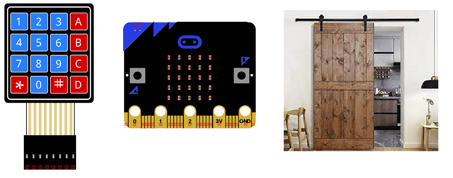
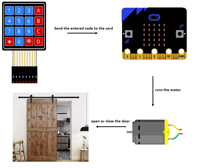
In this project, we will build a password-based door lock system by interfacing the Micro:bit board with a 4×4 keypad to enter the password.
We use a sliding door opening or closing by horizontal translation thanks to a 5V DC motor.
With this project we can build a security system that works with a password.
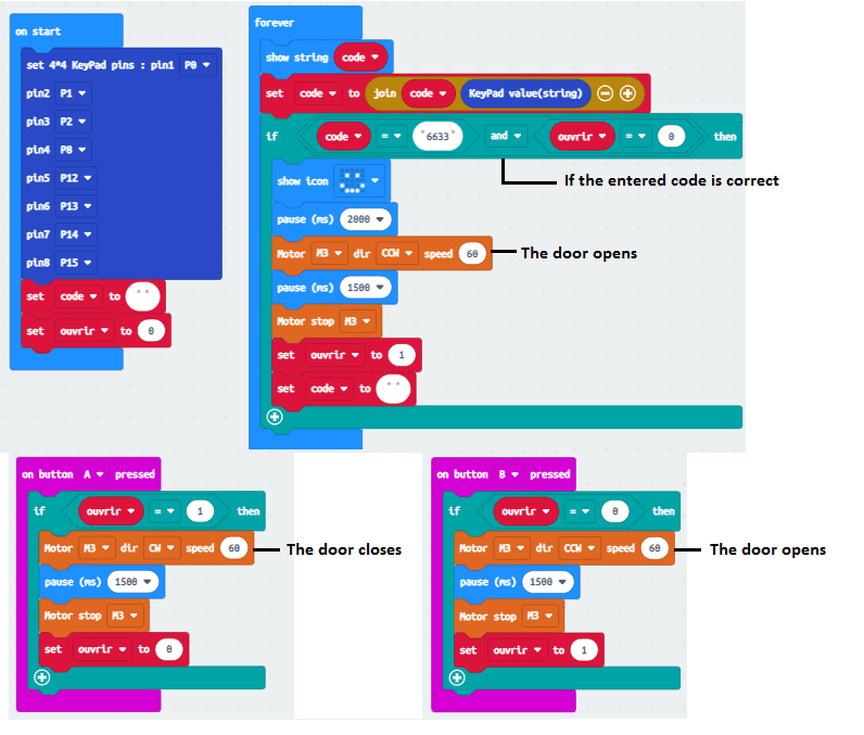
The door can be opened by two methods:
-
Method 1 based on password
-
Method 2 based on pressing button A
You can close the door by pressing button B
Description of how the door security system works
Composants nécessaires
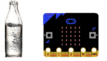
Micro:bit
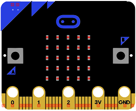
The BBC micro:bit is a small computing device developed by the BBC for use in computer education in the UK. It is a small, self-contained computer with an ARM Cortex-M0 processor, a 5×5 LED matrix, two buttons, and various sensors and input/output (I/O) devices. It is programmed using a web-based code editor and can be used to create a wide variety of interactive projects, such as games, displays, and sensors. The micro:bit is designed to be easy to use and accessible to beginners, with a focus on hands-on, experiential learning. It is also designed to be highly customizable and can be extended using various add-on boards and hardware.
4×4 keypad
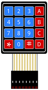
A 4×4 keypad is a device that consists of a grid of 4 rows and 4 columns of buttons, for a total of 16 buttons. It is commonly used as an input device for electronic projects and can be used to enter numbers, characters, or commands.
To use a 4×4 keypad, you will need to connect it to your project using wires. Each button on the keypad is connected to a row and a column on the keypad matrix. To determine which button has been pressed, you can scan the rows and columns of the matrix and look for a low voltage.
Micro:bit Driver Expansion Board
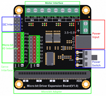
The Micro:bit Driver Expansion Board is an accessory for the Micro:bit microcontroller. It is a small circuit board that connects to the Micro:bit and provides additional features and capabilities.
The Micro:bit Driver Expansion Board typically includes a number of connectors and components that allow the Micro:bit to interface with a variety of external devices and sensors. This can include connectors for motors, servos, and other types of actuators, as well as connectors for sensors such as temperature sensors, light sensors, and proximity sensors.
The specific features and capabilities of the Micro:bit Driver Expansion Board will depend on the specific model and manufacturer. Some common features may include:
- Motor drivers: The expansion board may include H-bridge motor drivers, which allow the Micro:bit to control the speed and direction of DC motors.
- Servo connectors: The expansion board may include connectors for servo motors, which are commonly used in robotics applications.
- Sensor connectors: The expansion board may include connectors for a variety of sensors, such as temperature sensors, light sensors, and proximity sensors.
- I/O connectors: The expansion board may include additional input/output (I/O) connectors, such as analog inputs and outputs, that allow the Micro:bit to interact with a wider range of external devices.
The Micro:bit Driver Expansion Board is a useful accessory for those who want to expand the capabilities of their Micro:bit and build more complex projects.
DC motor
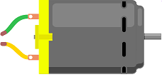
A 5V DC motor is a type of electric motor that operates on direct current (DC) voltage. It is a small motor that typically runs on 5V of power, although the voltage may vary slightly depending on the specific motor and the load it is driving. These motors are often used in small electronic devices, such as portable fans, toys, and robotic applications. They are generally very reliable, efficient, and simple to control, making them a popular choice for many different types of projects and applications.
connecting wires

Wires are used to transmit electrical signals and power to various components such as motors, sensors, and microcontrollers. It’s important to properly route and secure the wires to prevent tangles and damage. There are several methods for doing this, including using cable ties, clamps, and wire looms. It’s also a good idea to use different colors or labeling to identify the different wires and their functions. When connecting wires in a robot, it’s important to follow proper safety procedures, such as using the correct wire stripper and connectors, and wearing protective equipment such as gloves and safety glasses.
Assembly:
To carry out the assembly, we connect:
-
the 8 keyboard outputs to the 8 Micro:bit pins (P0, P1, P2, P8, P12, P13, P14, P15)
-
both motor terminals to 2 pin M3 of the Driver Expansion Board

Makecode program
Here is the Makecode program which allows the door to be opened or closed by the Micro:bit card.
You can also see

0 commentaire
Leave a comment


Recent tutorials


Most viewed tutorials


Most commented tutorials


Scroll to Top