
Presentation of Cooling system
A cooling system is a system that is designed to remove or dissipate heat from an object, area, or environment. Cooling systems can be found in a variety of applications, including automobiles, air conditioning systems, refrigeration systems, computers, and industrial machinery.
There are several types of cooling systems, including air-cooled, liquid-cooled, and thermoelectric cooling systems.
- Air-cooled systems use air to dissipate heat from the object or environment being cooled. This can be done by blowing air over the object or by using natural convection. Air-cooled systems are often used in automobiles and other vehicles to cool the engine, and in electronic devices to cool processors and other components.
- Liquid-cooled systems use a liquid, typically water or a water-glycol mixture, to dissipate heat from the object or environment being cooled. The liquid is circulated through a heat exchanger, where it absorbs heat from the object or environment, and then it is cooled before being circulated back through the heat exchanger. Liquid-cooled systems are often used in power plants, industrial processes, and high-performance computers.
- Thermoelectric cooling systems use the Peltier effect to remove heat from an object or environment. They use a thermoelectric module, which consists of a series of thermocouples that are connected in series and sandwiched between two ceramic plates. When a current is passed through the thermocouples, heat is transferred from one plate to the other, resulting in one plate getting hot and the other getting cold. Thermoelectric cooling systems are commonly used in small refrigeration and cooling applications, such as portable coolers, and temperature control in electronic devices.
Regardless of the type of cooling system, they all have the same goal which is to maintain a safe operating temperature for the object or equipment being cooled and to prevent overheating and damage.
Purpose of this project:
A cooling system controlled by a Micro:bit board can be implemented using a few different methods. One possibility is to use the Micro:bit to control a fan or a pump that is part of an air-cooled or liquid-cooled system. This can be done by connecting the fan or pump to a digital pin of the Micro:bit and using code to control the speed or on/off state of the fan or pump based on temperature readings from a sensor connected to the Micro:bit.
Another possibility is to use the Micro:bit to control a thermoelectric cooling system. This can be done by connecting the thermoelectric module to a digital pin of the Micro:bit and using code to control the current flowing through the module based on temperature readings from a sensor connected to the Micro:bit.
You can also use the Micro:bit to monitor the temperature of an object or environment and use that data to control the cooling system. This can be done by connecting a temperature sensor to the Micro:bit and using code to read the sensor data and control the cooling system based on the readings.
It’s worth mentioning that, Micro:bit alone doesn’t have the power to control large cooling systems, you would need additional components and hardware such as relays, transistors and other electronic parts.
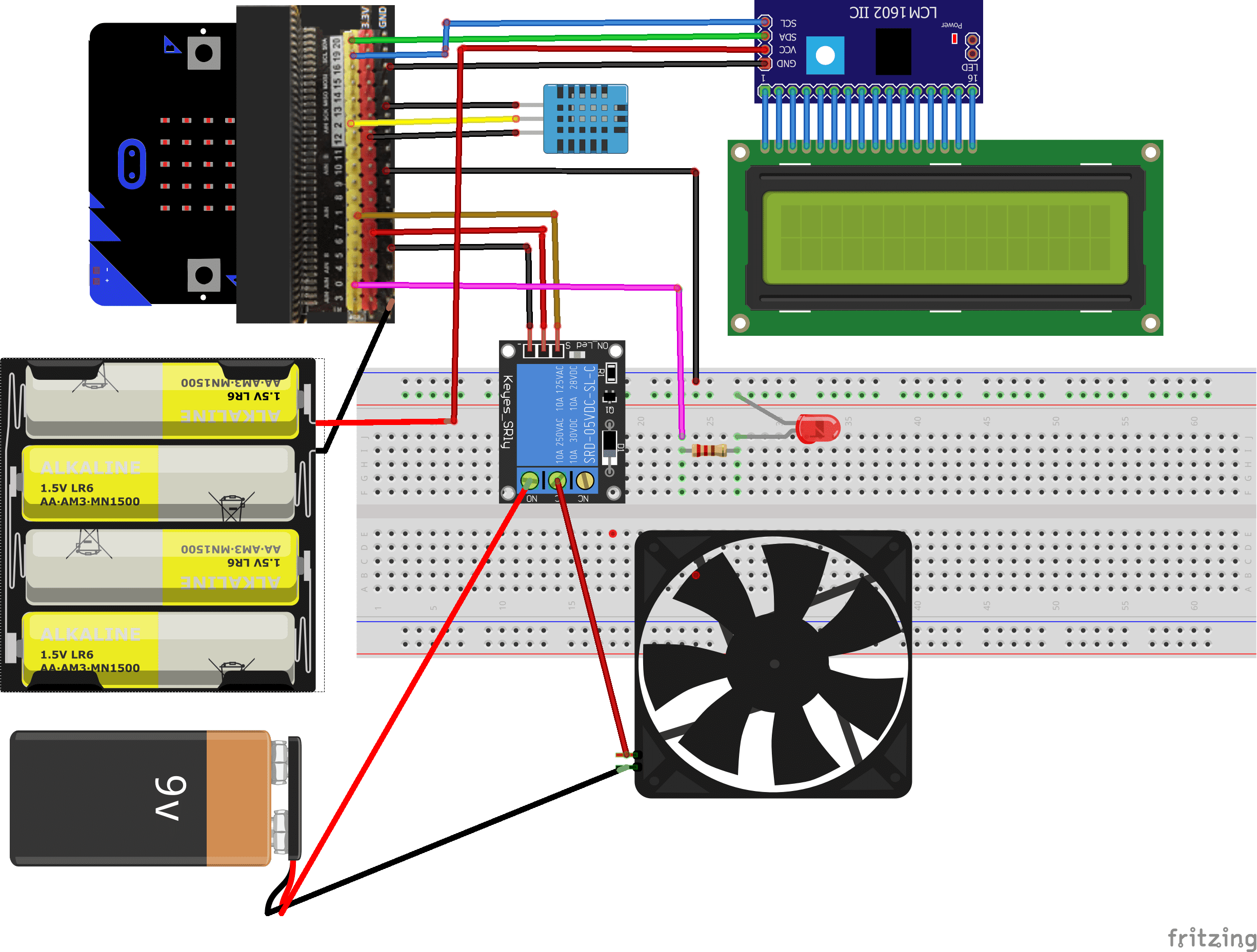
In this project a cooling system with Micro:bit will be realized. It mainly uses a DHT11 sensor, fan, LCD I2C 106A display and LED. When the micro:bit board detects a temperature > 27°C the red LED lights up and the fan starts to rotate to the temperature becomes < 26°C.
Required components
Micro:bit board
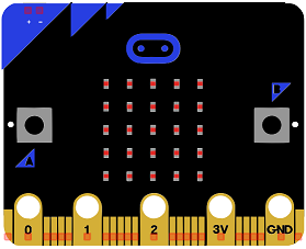
Micro:bit is a small, low-cost microcontroller board that was developed by the Micro:bit Educational Foundation for use in computer education. It is designed to be easy to use and accessible to a wide range of users, including children and beginners. The Micro:bit board measures about 4cm by 5cm and features a 25-pin edge connector, a 5×5 LED matrix, two programmable buttons, an accelerometer, a compass, a Bluetooth Low Energy (BLE) module, and a USB connector.
The Micro:bit is programmed using a variety of programming languages such as Python, JavaScript, and Microsoft Block Editor. It can be used to control a wide range of devices and projects, including robots, drones, lights, and more. The board can be powered by a USB cable or a 3V coin cell battery and can be programmed using a computer or mobile device.
The Micro:bit is widely used in education, providing a hands-on learning experience for students of all ages to learn computer programming, logic, and problem-solving. It’s also used by hobbyist and makers to create fun and interactive projects.
Microbit GPIO board
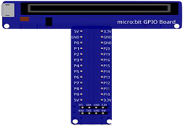
A Micro:bit GPIO (General Purpose Input/Output) Expansion Board is an accessory that can be used to extend the capabilities of a Micro:bit by providing additional input/output (I/O) pins. These pins can be used to connect sensors and actuators, such as LEDs, buttons, motors, and other electronic components.
The expansion board typically connects to the Micro:bit using a standard edge connector and provides a set of male headers that can be used to connect external components.
LCD I2C 160A display
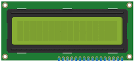
An LCD I2C 160A display is a type of liquid crystal display (LCD) that uses the I2C communication protocol to communicate with a microcontroller or other device. The “160A” in the name refers to the display’s physical size, with a display area of 160×128 pixels.
The I2C communication protocol allows multiple devices to communicate with a microcontroller using just two wires, SDA (Serial Data) and SCL (Serial Clock). This can be useful if you want to connect multiple devices to a microcontroller and conserve the number of pins required.
To use an LCD I2C 160A display with a Micro:bit board, you would need to connect the display to the Micro:bit‘s SDA and SCL pins, and then use code to communicate with the display over the I2C bus. The Micro:bit board has built-in I2C support, so you can use the Micro:bit’s I2C library to send commands and data to the display.
You can use the Micro:bit‘s built-in LCD library to control and display different characters on the display. By using the Micro:bit‘s library you can draw shapes, characters, and even create simple animations on the display.
DHT11 sensor
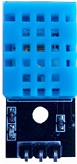
A DHT11 sensor is a low-cost digital temperature and humidity sensor. It can be used in combination with a Micro:bit board to control a cooling system.
One way to use the DHT11 sensor to control a cooling system with a Micro:bit board is to read the temperature and humidity data from the sensor, and then use that data to control the cooling system based on the temperature and humidity levels. For example, if the temperature or humidity is too high, the Micro:bit can send a signal to turn on the cooling system, and if the temperature and humidity are within a certain range, the Micro:bit can send a signal to turn off the cooling system.
You could connect the DHT11 sensor to the Micro:bit board and use the Micro:bit’s built-in support for the DHT11 sensor to read the temperature and humidity data. You can then use this data to control the cooling system.
Small fan of 5V
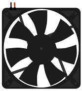
A small fan that runs on 5V is a type of electrical fan that is powered by a 5-volt power source. These types of fans are typically used in small electronic devices and projects, such as cooling systems, computer cases, and other similar applications.
To control a small fan of 5V with a Micro:bit board, you would need to connect the fan to the Micro:bit’s power pins, and then use code to control the power to the fan. The Micro:bit board can provide 3.3V and 0V, but not 5V. So you will need to use a voltage regulator (such as LM7805) or a transistor to step-up the voltage to 5V.
You can use the Micro:bit’s built-in digital output pins to send a signal to the voltage regulator or transistor to turn the fan on or off. Additionally, you could use the Micro:bit’s built-in temperature sensor to measure the temperature and use that data to control the fan speed.
Relay
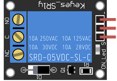
A relay is an electrically operated switch that can be controlled by a small current, allowing it to switch on or off a larger current. In this case, the relay is used to control the power to the fan, turning it on or off as needed.
To control a fan with a relay and a Micro:bit board, you would need to connect the fan to the relay and the relay to the Micro:bit board. The Micro:bit board can be used to send a signal to the relay, which will then turn the fan on or off depending on the signal received.
You can use the Micro:bit‘s built-in digital output pins to send a signal to the relay, which will then switch the fan on or off. Additionally, you could use the Micro:bit‘s built-in temperature sensor to measure the temperature and use that data to control the fan speed.
1 resistance 220Ω
![]()
Resistance is a measure of a material’s opposition to the flow of electric current. It is measured in ohms (Ω) and is represented by the symbol “R”. The more resistance a material has, the less current will flow through it when a given voltage is applied. Conversely, the less resistance a material has, the more current will flow through it when a given voltage is applied.
1 red LED
![]()
A red LED (light-emitting diode) is a type of diode that emits light in the red part of the visible spectrum when an electric current is passed through it. LEDs are semiconductor devices that convert electrical energy into light energy. They are widely used in various electronic devices and systems, such as displays, indicator lights, flashlights, and traffic signals.
connecting wires

Connecting wires are used to connect various components in an electronic circuit. They allow for the transfer of electricity, data, or signals between different devices and components.
When connecting wires to an Arduino or other microcontroller, it is important to pay attention to the correct pinout. The pinout refers to the arrangement of pins on the microcontroller and the corresponding function of each pin. The Arduino pinout can be found in the documentation provided by the manufacturer, or in various resources available online.
test plate

A test plate, also known as a test jig, is a device used to test electronic circuits and components. It is a board or plate that has been designed to hold and connect various components and devices in a specific configuration, allowing for the easy testing and measurement of their performance.
A test plate can be used to test various types of electronic circuits and components, such as microcontrollers, sensors, and actuators. It typically includes connectors and sockets for connecting wires, power supply and measurement devices such as multimeters, oscilloscopes, and power supplies.
2 batteries of 9V
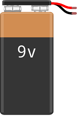
A 9V battery is a type of primary cell battery that is commonly used in small electronic devices such as remote controls, smoke detectors, and portable radios. It is known for its compact size and relatively high voltage output. The 9V battery is also known as a “transistor battery” because it was originally designed for use in portable transistor radios.
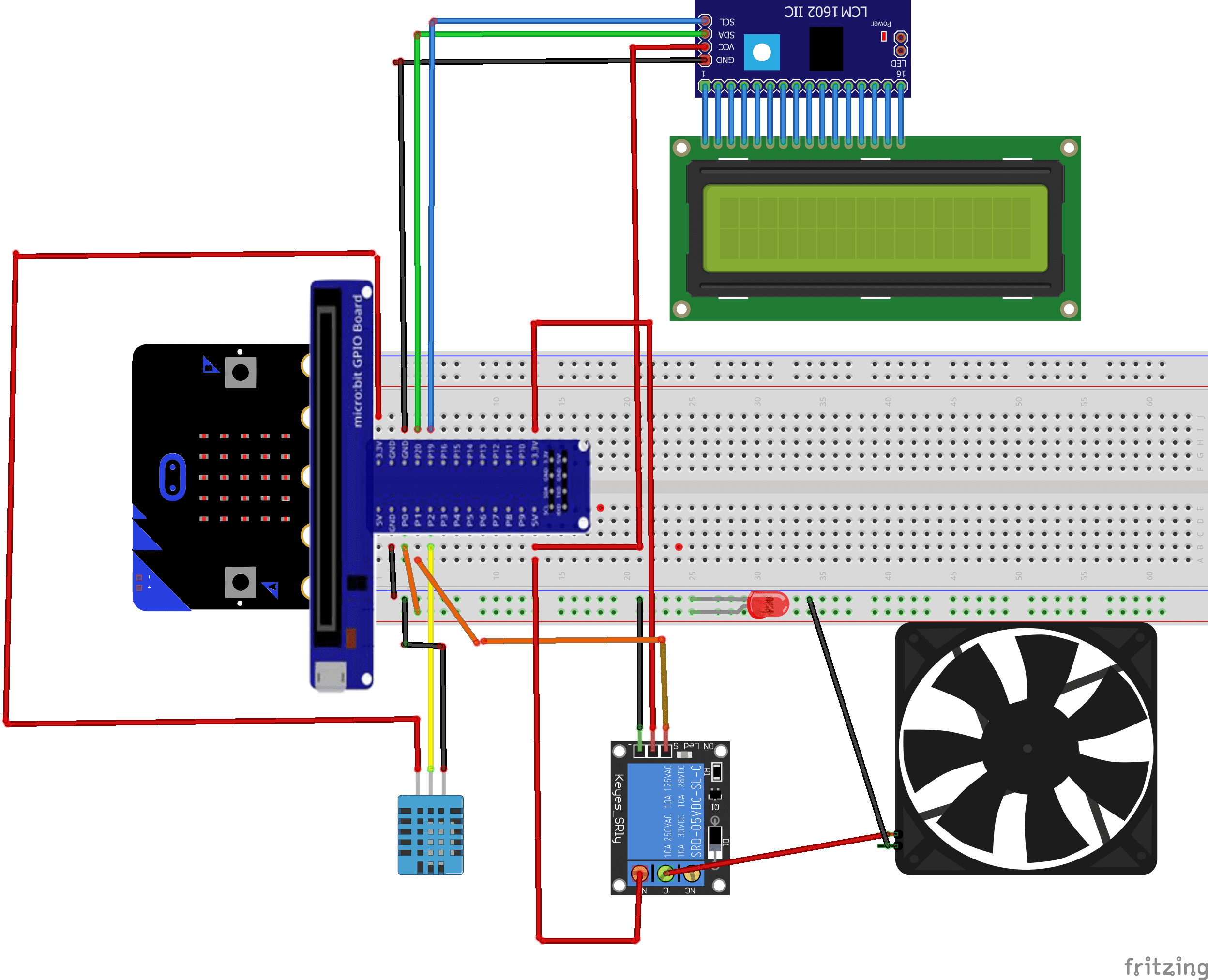
Mounting
To complete the mounting, you can connect
- the red LED to pin P0 of the micro:bit
- the pin S of the relay to pin P1 of the micro:bit board
- the pin DATA of the DTH11 sensor to pin P2 of the micro:bit board
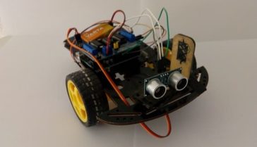
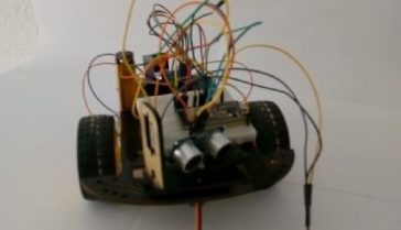
Les méthodes de montage sont nombreuses et en voilà des exemples :
Mounting (1)
Mounting (2)
Makecode program
Here is the program makecode of the cooling system.
Note: you have to go to Extensions to import the extension DTH11/DTH22 and I2c_LCD1602

You can also see

0 commentaire
Leave a comment


Recent tutorials


Most viewed tutorials


Most commented tutorials


Scroll to Top